Wio GPS – also called Wio Tracker – is an Arduino compatible board based on Microchip Atmel SAMD21 MCU with GPS, Bluetooth, GSM/GPRS connectivity, as well as several Grove connectors to connect sensors and modules for your IoT project. SeeedStudio sent me a sample for evaluation, so I’ve tested it, and reported my experience below by testing some of the Arduino sketches.
Wio Tracker Unboxing
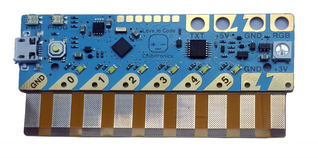
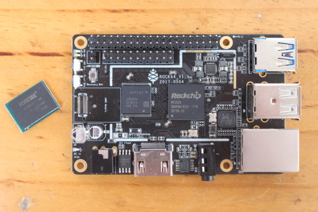
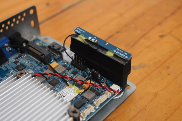
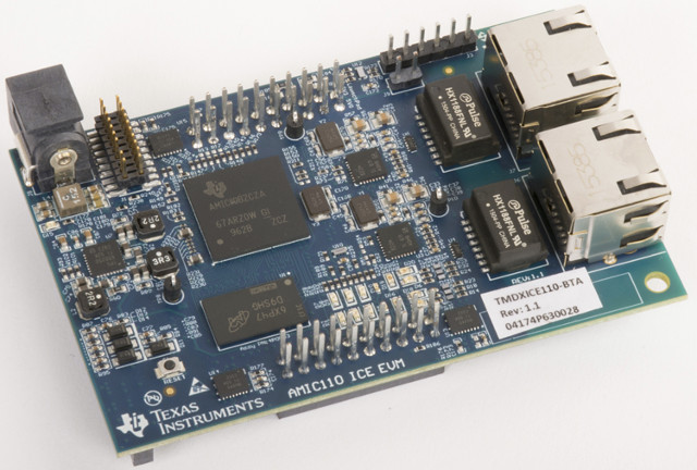
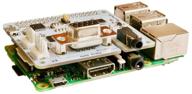
All I got in the package was Wio GPS tracker v1.1 board. The top includes the Atmel MCU, an RGB LED, a microphone and 3.5mm AUX jack to make phone calls, a user and power button, a micro USB port for power and programming, a small 2-pin connector for a battery, and 6 Grove connectors for digital, serial, I2C and analog modules.
![]()
Click to Enlarge
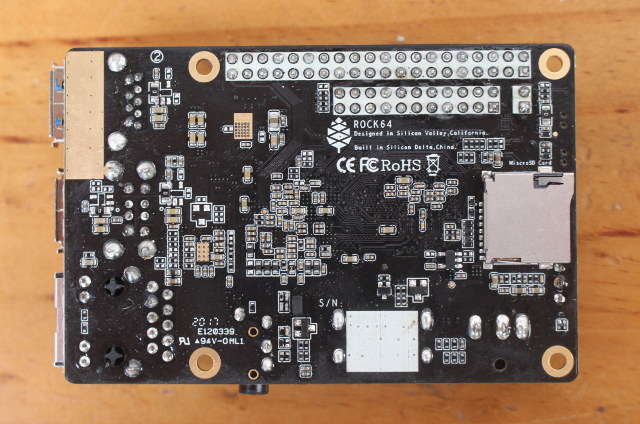
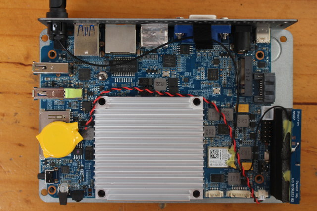
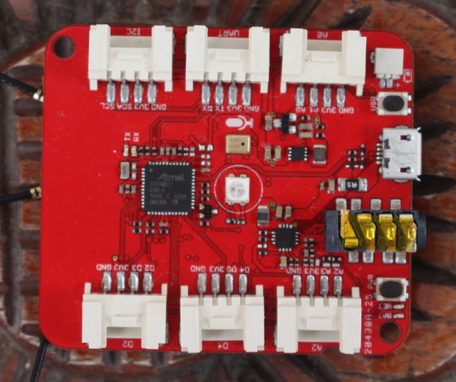
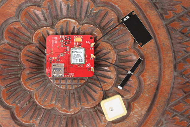
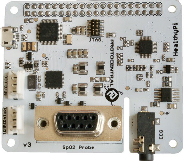
The other side of the board comes with Quectel MC20 module that handles Bluetooth, GPS and GSM, a dual use micro SD card and nano SIM slot, and the GPS, 2G, and Bluetooth antennas. We can also see -/+ footprints close to connect speakers close to the OSHW logo.
![]()
Click to Enlarge
Getting Started with Wio GPS Tracker with Arduino IDE
I’ve been following Wio GPS Board Wiki for this part of the review, and as we’ll soon discovered I’ve had a rather mixed experience.
First, you’ll need a micro USB to USB cable to connect the board to Windows/Linux/Mac computer. This is the kernel output I got from Ubuntu 16.04:
|
|
[27730.518478] usb 5-3: new full-speed USB device number 3 using ohci-pci
[27730.720494] usb 5-3: New USB device found, idVendor=2886, idProduct=800e
[27730.720497] usb 5-3: New USB device strings: Mfr=1, Product=2, SerialNumber=3
[27730.720499] usb 5-3: Product: Wio GPS Board
[27730.720501] usb 5-3: Manufacturer: Seeed Studio
[27730.723714] cdc_acm 5-3:1.0: ttyACM0: USB ACM device
|
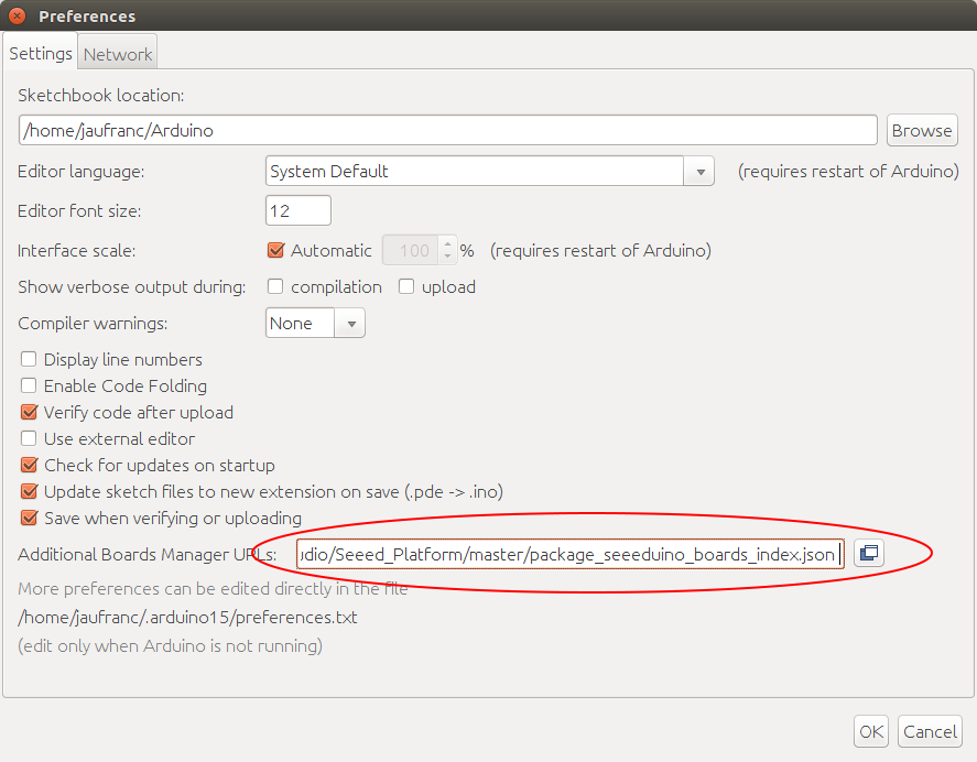
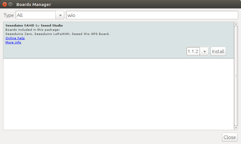
After installing Arduino IDE for your operating system, we can add Seeduino boards to the IDE, by going to File->Preferences and pasting the link https://raw.githubusercontent.com/Seeed-Studio/Seeed_Platform/master/package_seeeduino_boards_index.json into Additional Boards Manager URL field, and clicking OK.![]() Now go to Tools->Boards->Boards Manager search for wio, and install Seeduino SAMD by Seeed Studio.
Now go to Tools->Boards->Boards Manager search for wio, and install Seeduino SAMD by Seeed Studio.
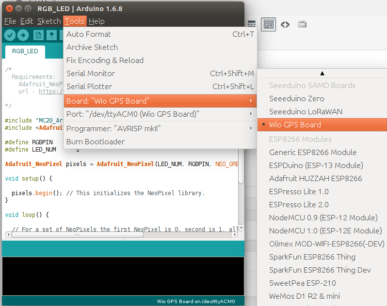
![]() You can also install Adafruit Neopixel by going to to Sketch->Manage Libraries->Include Library, or importing the zip file. After that point, I decided to check whether I could find “Wio Tracker” in the list of boards as indicated in the Wiki, but there was no such board so I selected Wio GPS Board, and selected port /dev/ttyACM0 (Wio GPS Board) port.
You can also install Adafruit Neopixel by going to to Sketch->Manage Libraries->Include Library, or importing the zip file. After that point, I decided to check whether I could find “Wio Tracker” in the list of boards as indicated in the Wiki, but there was no such board so I selected Wio GPS Board, and selected port /dev/ttyACM0 (Wio GPS Board) port.
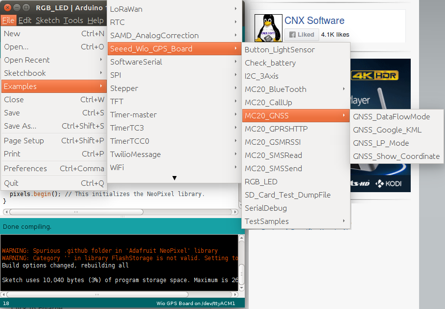
![]() Then I went to check for sample sketches, and found some in Examples->Seeed_Wio_GPS_Board for the all key features of the board. So I tried a bunch of them including RGB_LED, Bluetooth, GNSS (GPS), and GSM (Send SMS), and only the Bluetooth sample would work.
Then I went to check for sample sketches, and found some in Examples->Seeed_Wio_GPS_Board for the all key features of the board. So I tried a bunch of them including RGB_LED, Bluetooth, GNSS (GPS), and GSM (Send SMS), and only the Bluetooth sample would work.
![]()
Click to Enlarge
By I went back to the Wiki, and found out I add to import Wio Tracker library too, which I did, and I had another very similar sets of samples for MC20_GPS_Traker-master.
![]() I’m not exactly sure we have two separate sets of nearly identical samples, but let’s see if I have more like with samples in MC20_GPS_Tracker-master folder.
I’m not exactly sure we have two separate sets of nearly identical samples, but let’s see if I have more like with samples in MC20_GPS_Tracker-master folder.
Blink.ino is supposed to blink the RGB using blue color:
#define RGBPIN 10
#define LED_NUM 1
Adafruit_NeoPixel pixels = Adafruit_NeoPixel(LED_NUM, RGBPIN, NEO_GRB + NEO_KHZ800);
void setup() {
pixels.begin(); // This initializes the NeoPixel library.
}
void loop() {
// For a set of NeoPixels the first NeoPixel is 0, second is 1, all the way up to the count of pixels minus one.
// pixels.Color takes RGB values, from 0,0,0 up to 255,255,255
pixels.setPixelColor(0, pixels.Color(0,0,100)); // Moderately bright blue color.
pixels.show(); // This sends the updated pixel color to the hardware.
delay(1000); // Wait for 1 second
pixels.setPixelColor(0, pixels.Color(0,0,0)); // Turn off the led.
pixels.show();
delay(1000);
}
1
2
3
4
5
6
7
8
9
10
11
12
13
14
15
16
17
18
19
20
21
22
23
24
|
#include “MC20_Arduino_Interface.h”
#include <Adafruit_NeoPixel.h>
#define RGBPIN 10
#define LED_NUM 1
Adafruit_NeoPixel pixels = Adafruit_NeoPixel(LED_NUM, RGBPIN, NEO_GRB + NEO_KHZ800);
void setup() {
pixels.begin(); // This initializes the NeoPixel library.
}
void loop() {
// For a set of NeoPixels the first NeoPixel is 0, second is 1, all the way up to the count of pixels minus one.
// pixels.Color takes RGB values, from 0,0,0 up to 255,255,255
pixels.setPixelColor(0, pixels.Color(0,0,100)); // Moderately bright blue color.
pixels.show(); // This sends the updated pixel color to the hardware.
delay(1000); // Wait for 1 second
pixels.setPixelColor(0, pixels.Color(0,0,0)); // Turn off the led.
pixels.show();
delay(1000);
}
|
I could upload the program to the board with the following warning messages:
|
|
WARNING: Spurious .github folder in ‘Adafruit NeoPixel’ library
WARNING: Category ” in library FlashStorage is not valid. Setting to ‘Uncategorized’
WARNING: Spurious .github folder in ‘Adafruit NeoPixel’ library
Multiple libraries were found for “MC20_Arduino_Interface.h”
Used: /home/jaufranc/Arduino/libraries/MC20_GPS_Tracker-master
Not used: /home/jaufranc/.arduino15/packages/Seeeduino/hardware/Seeeduino_SAMD/1.1.2/libraries/Seeed_Wio_GPS_Boardl
|
The RGB LED did not work. So I tried to remove Adafruit Neopixel library, same results. Finally I checked schematics to confirm the RGB LED is indeed connected to D10, and inserted some println debug code to make sure the program is running properly. Everything seems right, but the RGB LED would not blink. I’ve contacted the company, but unsurprinsgly they don’t work during the week-end.
Let’s move on with BT_CLientHandle.ino sketch that should allow us to pair the board with your phone. The code is relatively simple for this task:
// GPSTracker gpsTracker = GPSTracker();
BlueTooth bt = BlueTooth();
int bt_state = -1;
int device_id;
void setup() {
SerialUSB.begin(115200);
while(!SerialUSB);
bt.Power_On();
SerialUSB.println(“nrMC20 power On!”);
bt.BTPowerOn();
SerialUSB.println(“nrBT power On!”);
while(IDLE != (bt_state = bt.getBTState())){
SerialUSB.print(“State: “);
SerialUSB.println(bt_state);
delay(1000);
}
SerialUSB.println(“Waitting for connecting…”);
int result = bt.loopHandle();
SerialUSB.print(“Connect result: “);
result != 0? SerialUSB.println(“Failed!”):SerialUSB.println(“Success!”);
}
void loop() {
/* Debug */
if(SerialUSB.available()){
serialMC20.write(SerialUSB.read());
}
if(serialMC20.available()){
SerialUSB.write(serialMC20.read());
}
}
1
2
3
4
5
6
7
8
9
10
11
12
13
14
15
16
17
18
19
20
21
22
23
24
25
26
27
28
29
30
31
32
33
34
35
36
37
38
39
|
#include “MC20_Common.h”
#include “MC20_BT.h”
// GPSTracker gpsTracker = GPSTracker();
BlueTooth bt = BlueTooth();
int bt_state = -1;
int device_id;
void setup() {
SerialUSB.begin(115200);
while(!SerialUSB);
bt.Power_On();
SerialUSB.println(“nrMC20 power On!”);
bt.BTPowerOn();
SerialUSB.println(“nrBT power On!”);
while(IDLE != (bt_state = bt.getBTState())){
SerialUSB.print(“State: “);
SerialUSB.println(bt_state);
delay(1000);
}
SerialUSB.println(“Waitting for connecting…”);
int result = bt.loopHandle();
SerialUSB.print(“Connect result: “);
result != 0? SerialUSB.println(“Failed!”):SerialUSB.println(“Success!”);
}
void loop() {
/* Debug */
if(SerialUSB.available()){
serialMC20.write(SerialUSB.read());
}
if(serialMC20.available()){
SerialUSB.write(serialMC20.read());
}
}
|
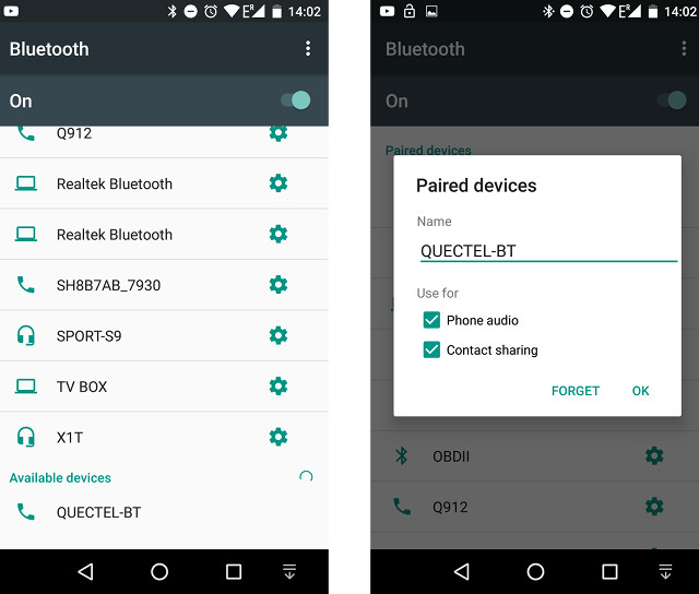
I could see QUECTEL-BT with my Android phone, and had no problem to pair the board.
![]()
The serial output with pairing, and disconnecting events shows some of the AT commands used:
Connect result: Success!
AT
+QBTPAIRCNF: 1,1,0,”Apollo Lite”,9471BC2FEFAD
+QBTCONN: 1,0,”Apollo Lite”,9471BC2FEFAD,”HF_PROFILE”
+QBTIND: “disc”,0,1,”Apollo Lite”,9471BC2FEFAD,”HF_PROFILE”
|
|
+QBTIND: “pair”,“Apollo Lite”,9471BC2FEFAD,446331
Connect result: Success!
AT
+QBTPAIRCNF: 1,1,0,“Apollo Lite”,9471BC2FEFAD
+QBTCONN: 1,0,“Apollo Lite”,9471BC2FEFAD,“HF_PROFILE”
+QBTIND: “disc”,0,1,“Apollo Lite”,9471BC2FEFAD,“HF_PROFILE”
|
I also tried to connect a speaker to the AUX port of the board to see if I could use it as Bluetooth speaker, but it did not work, so some more code and a different Bluetooth audio profile (not HF_PROFILE) are likely required. All I could hear was dial-up modem sounds from the speakers. But still, we can tick this Bluetooth test as success.
Time for a GPS test. GNSS_Show_Coordinate.ino sketch is supposed to output latitude and longitude to the serial console, and again the code to achieve this is still fairly simple:
GNSS gnss = GNSS();
void setup() {
SerialUSB.begin(115200);
// while(!SerialUSB);
gnss.Power_On();
SerialUSB.println(“nrPower On!”);
while(!gnss.open_GNSS(EPO_QUICK_MODE)){
delay(1000);
}
SerialUSB.println(“Open GNSS OK.”);
}
void loop() {
char buffer[64];
if(gnss.getCoordinate()){
SerialUSB.print(“GNSS: “);
SerialUSB.print(gnss.longitude, 6);
SerialUSB.print(“,”);
SerialUSB.println(gnss.latitude, 6);
SerialUSB.print(gnss.str_longitude);
SerialUSB.print(“,”);
SerialUSB.println(gnss.str_latitude);
} else{
SerialUSB.println(“Error!”);
}
delay(1000);
}
1
2
3
4
5
6
7
8
9
10
11
12
13
14
15
16
17
18
19
20
21
22
23
24
25
26
27
28
29
30
31
32
33
34
35
36
37
|
#include “MC20_Common.h”
#include “MC20_Arduino_Interface.h”
#include “MC20_GNSS.h”
GNSS gnss = GNSS();
void setup() {
SerialUSB.begin(115200);
// while(!SerialUSB);
gnss.Power_On();
SerialUSB.println(“nrPower On!”);
while(!gnss.open_GNSS(EPO_QUICK_MODE)){
delay(1000);
}
SerialUSB.println(“Open GNSS OK.”);
}
void loop() {
char buffer[64];
if(gnss.getCoordinate()){
SerialUSB.print(“GNSS: “);
SerialUSB.print(gnss.longitude, 6);
SerialUSB.print(“,”);
SerialUSB.println(gnss.latitude, 6);
SerialUSB.print(gnss.str_longitude);
SerialUSB.print(“,”);
SerialUSB.println(gnss.str_latitude);
} else{
SerialUSB.println(“Error!”);
}
delay(1000);
}
|
But all I got in the serial output was the following:
RDY
+CFUN: 1
+CPIN: NOT INSERTED
IFGCNT=2
OK
AT+CREG?
+CREG: 0,4
OK
AT+CREG?
+CREG: 0,0
OK
AT+CREG?
+CREG: 0,0
OK
AT+CREG?
+CREG: 0,0
OK
AT+CREG?
+CREG: 0,0
OK
AT+CREG?
+CREG: 0,0
1
2
3
4
5
6
7
8
9
10
11
12
13
14
15
16
17
18
19
20
21
22
23
24
25
26
27
28
29
30
31
|
Power On!
RDY
+CFUN: 1
+CPIN: NOT INSERTED
IFGCNT=2
OK
AT+CREG?
+CREG: 0,4
OK
AT+CREG?
+CREG: 0,0
OK
AT+CREG?
+CREG: 0,0
OK
AT+CREG?
+CREG: 0,0
OK
AT+CREG?
+CREG: 0,0
OK
AT+CREG?
+CREG: 0,0
|
With +CREG: 0,0 shown over and over. We can find the different AT Command sets (and EAGLE schematics) in the resources directory in Github. One of the document reports that AT+CREG? is a read command to retrieve network registration status, and the two numbers referred as <n> and <stat> are set to 0,0 meaning that:
- Disable network registration unsolicited result code
- Not registered, ME is not currently searching a new network to register on
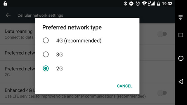
I firstly did the test indoors, and although previously I could get a signal indoors with NavSpark mini board, I still went outside in case it was a signal problem, but the result was just the same. So maybe the program is stuck somewhere because I had not inserted a SIM card yet. Since I was not sure whether my operator still supported 2G, I forced my Android phone to use 2G, and the phone did get a signal using “E” instead of the usual 3G, and I could send an SMS and make a phone call over 2G network (I think).
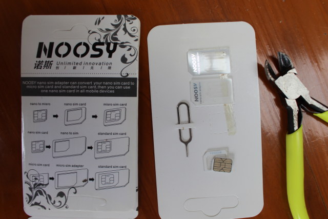
![]() So I took out the SIM card from my phone, and …. I could not insert right away simply because my SIM card was cut out as a micro SIM, but the board requires a nano SIM. Luckily, I purchased nano/micro SIM card adapters a while ago as I knew sooner or later I would have this little first world problem. You can find those for less than $1 on eBay, so even if you don’t need them right now, it might be a good idea to get some.
So I took out the SIM card from my phone, and …. I could not insert right away simply because my SIM card was cut out as a micro SIM, but the board requires a nano SIM. Luckily, I purchased nano/micro SIM card adapters a while ago as I knew sooner or later I would have this little first world problem. You can find those for less than $1 on eBay, so even if you don’t need them right now, it might be a good idea to get some.
![]()
Click to Enlarge
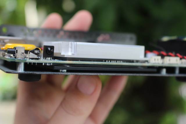
Once I cut out my SIM card so that it fits into the micro SIM to nano SIM adapter that I will need to use when I put back the SIM card into my smartphone, I inserted the nano SIM and a micro SD card at the same time, as the picture below shows with the white band right above the 4GB micro SD card being the nano SIM card. I did not know they made those, as I’ve only seen shared slots in the past.
![]()
I reran the GPS sample program, and the serial output changes a bit, but still no longitude and latitude info:
+CFUN: 1
+CPIN: READY
AT+CREG?
+CREG: 0,2
OK
Call Ready
AT+CREG?
+CREG: 0,2
OK
SMS Ready
AT+CREG?
+CREG: 0,5
OK
AT+CREG?
+CREG: 0,5
OK
AT+QGNSSC?
+QGNSSC: 0
OK
AT+QGNSSC=1
OK
AT+QGNSSC?
+QGNSSC: 1
OK
AT+CREG?NT=2
OK
+CREG: 0,5
OK
AT+CREG?
+CREG: 0,5
OK
AT+CREG?
+CREG: 0,5
OK
1
2
3
4
5
6
7
8
9
10
11
12
13
14
15
16
17
18
19
20
21
22
23
24
25
26
27
28
29
30
31
32
33
34
35
36
37
38
39
40
41
42
43
44
45
46
47
48
49
50
51
|
RDY
+CFUN: 1
+CPIN: READY
AT+CREG?
+CREG: 0,2
OK
Call Ready
AT+CREG?
+CREG: 0,2
OK
SMS Ready
AT+CREG?
+CREG: 0,5
OK
AT+CREG?
+CREG: 0,5
OK
AT+QGNSSC?
+QGNSSC: 0
OK
AT+QGNSSC=1
OK
AT+QGNSSC?
+QGNSSC: 1
OK
AT+CREG?NT=2
OK
+CREG: 0,5
OK
AT+CREG?
+CREG: 0,5
OK
AT+CREG?
+CREG: 0,5
OK
|
+QGNSSC:1 means the GNSS module is powered on so that’s good news I guess.
+CREG: 0,2 means the SIM card is registered, and in home network, but then it will switch to +CREG:0,5 meaning the SIM card is registered and roaming. Not really re-assuring.
They also have a more complex sample called GNSS_Google_KML.ino, that will get coordinate display them in OLED display attached to the board, and save data into a gps.txt into the SD card with raw longitude and latitude data that can be inserted into a Google KML file. A GoogleMapDemo.ino sketch will upload your coordinates to ziladuo.com website. That’s provided it works of course… and considering the simplest sample GNSS would not work. I gave up on GPS/GNSS tests.
Last try was with the GSM function with the send SMS sample (MC20_SMSSend.ino) that will send “Hello MC20!!” message to the phone number of your choice”. Again it’s very easy to program:
#define RGBPIN 10
const char message[128] = “Hello MC20!”;
GPSTracker gpsTracker = GPSTracker();
void setup() {
pinMode(RGBPIN, OUTPUT);
digitalWrite(RGBPIN, LOW);
SerialUSB.begin(115200);
while(!SerialUSB);
gpsTracker.Power_On();
SerialUSB.println(“Power On!”);
if(!gpsTracker.waitForNetworkRegister())
{
SerialUSB.println(“Network error!”);
return;
}
gpsTracker.sendSMS(“xxxxxxxxxxx”, “Hello MC20!”); /* replace xxxxxx with destination phone number */
}
void loop() {
/* Debug */
if(SerialUSB.available()){
serialMC20.write(SerialUSB.read());
}
if(serialMC20.available()){
SerialUSB.write(serialMC20.read());
}
}
1
2
3
4
5
6
7
8
9
10
11
12
13
14
15
16
17
18
19
20
21
22
23
24
25
26
27
28
29
30
31
32
33
34
35
36
37
38
|
#include “MC20_Common.h”
#include “MC20_Arduino_Interface.h”
#define RGBPIN 10
const char message[128] = “Hello MC20!”;
GPSTracker gpsTracker = GPSTracker();
void setup() {
pinMode(RGBPIN, OUTPUT);
digitalWrite(RGBPIN, LOW);
SerialUSB.begin(115200);
while(!SerialUSB);
gpsTracker.Power_On();
SerialUSB.println(“Power On!”);
if(!gpsTracker.waitForNetworkRegister())
{
SerialUSB.println(“Network error!”);
return;
}
gpsTracker.sendSMS(“xxxxxxxxxxx”, “Hello MC20!”); /* replace xxxxxx with destination phone number */
}
void loop() {
/* Debug */
if(SerialUSB.available()){
serialMC20.write(SerialUSB.read());
}
if(serialMC20.available()){
SerialUSB.write(serialMC20.read());
}
}
|
But sadly I could not send an SMS, as the function waitForNetworkRegister failed:
|
|
Power On!
Network error!
ATE1 E0
OK
|
I had to end my testing there. I could not remove the nano SIM card with my hands, and I had to use a pair tweezers to get it out by pushing those the small holes on top of the slot mechanism.
So overall my experience with the board was quite catastrophic with only Bluetooth working, and GPS, 2G GSM, and even the RGB LED sample all failing. I also often had trouble uploading the code to the board with messages like:
|
1
|
No device found on ttyACM0
|
or (even after having close to the serial terminal for a while):
|
|
Caused by: processing.app.SerialException: Error touching serial port ‘/dev/ttyACM0′.
at processing.app.Serial.touchForCDCReset(Serial.java:87)
at cc.arduino.packages.uploaders.SerialUploader.uploadUsingPreferences(SerialUploader.java:130)
... 6 more
Caused by: jssc.SerialPortException: Port name - /dev/ttyACM0; Method name - openPort(); Exception type - Port busy.
at jssc.SerialPort.openPort(SerialPort.java:164)
at processing.app.Serial.touchForCDCReset(Serial.java:81)
|
So I often had to re-try and re-try to successfully upload the code to the board. I’m sure there must be an explanation for all the issues I had. I can see they tested it in Windows, but I’m using Ubuntu 16.04, so maybe that could be one reason?
Having said that, if the board actually worked, I really like what SeeedStudio has done, as it looks really easy to program the board with GPS, Bluetooth, or 2G data, SMS, calls, and you can add Grove Sensors to make pretty more advanced IoT projects. The company also provides a more practical sample with their “Wild Adventure Tracker” demo reporting sending GPS coordinates over SMS when a shock occurs. The source code on Github with a video showing the results below.
[embedded content]
The company is also working on a 4G version, and I’ll probably have a chance to give it another try once it is released. If you are interested in Wio GPS Tracker board, you can pre-order it for $24.95 including all three antennas.
Share Tweet Pin Mail Tweet Wio GPS – also called Wio Tracker – is an Arduino compatible board based on Microchip Atmel SAMD21 MCU with GPS, Bluetooth, GSM/GPRS connectivity, as…
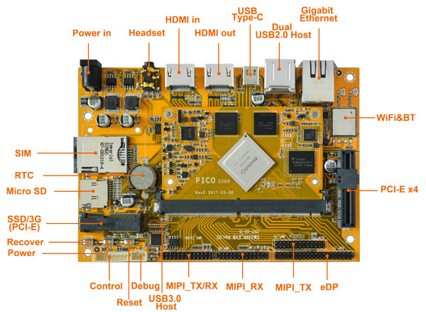
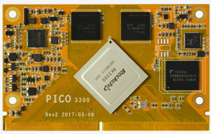 PICO3399 SoM specifications:
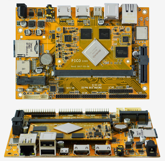 You can get started quickly with the CPU module using EM3399 development board with the following specifications: