This is a guest post by Leonardo Graboski Veiga, Field Application Engineer, Toradex Brasil Introduction Computer vision (CV) is everywhere – from cars to surveillance and production lines, the need…
↧
Getting Started with OpenCV for Tegra on NVIDIA Tegra K1, CPU vs GPU Computer Vision Comparison
↧
Melon S3 FPGA Arduino & Raspberry Pi Compatible Board is Programmable over WiFi using ESP8266 WiSoC
Q-Wave Systems, an embedded systems company based in Thailand, has designed Melon S3 FPGA board powered by a Xilinx Spartan 3E FPGA with WiFi connectivity added through a ESP8266 module programmable with the Arduino IDE , and featuring two Raspberry Pi compatible headers. The FPGA bitstream can be updated over WiFi, and does not require a JTAG debugger.
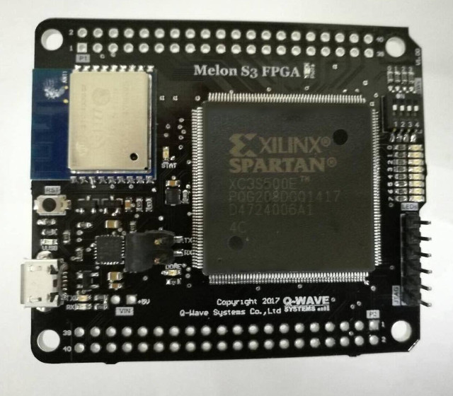
Melon S3 FPGA Prototype
Melon S3 FPGA specifications:
- FPGA – Xilinx Spartan XC3S500E FPGA with 500K gates, 73Kb Distributed RAM, 4 Digital Clock Manager (DCM), 20 Multipliers (18×18), 360 Kb Block RAM
- WiFi module – WROOM-2 with Espressif ESP8266 32-bit MCU @ 80 MHz supporting 802.11 b/g/n WiFi.
- Storage – 4MB SPI flash in total with 1MB for ESP8266, 3 MB for FPGA
- Expansion – 2x 40-pin Raspberry Pi compatible headers; 3.3V tolerant
- Debugging – Onboard USB-UART Silicon Labs CP2104 for configuration, debugging and power; 6-pin JTAG port for debugging/programming
- Misc – 8x Users LEDs, 4x DIP switch user button, 1x reset button, on-board 50 MHz FPGA clock
- Power Supply – 5V via micro USB port
- Dimensions – 65 mm x 56.5 mm x 10 mm
- Weight – 20g
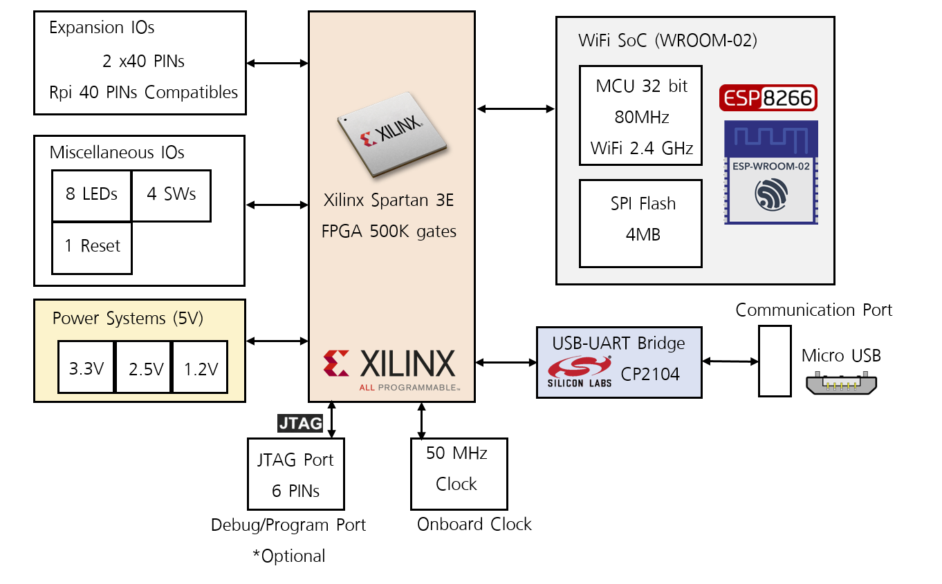
Block Diagram for Melon S3 FPGA – Click to Enlarge
The board can be used in standalone, but it’s also compliant with Raspberry Pi HAT form factor, and can be inserted on top of Raspberry Pi boards with 40-pin headers, which in theory would allow you to run the Arduino IDE directly on Raspberry Pi to program Melon S3 FPGA board.
You can also program the FPGA using development tools such as Xilinx ISE Webpack (free), MATLAB HDL Coder/HDL Verifier and National Instruments LabVIEW FPGA Toolkit, and upload the resulting bitstream using the board’s web interface.
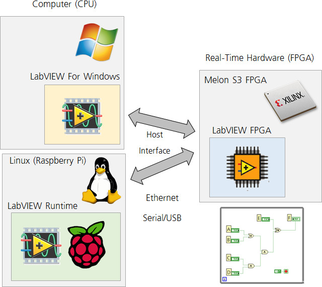
Melon S3 FPGA Labview Programming with Raspberry Pi / Computer
The board is available via a sort of self-organized crowdfunding campaign, with at least 50 backers required by May 31. At the latest update, they had 74 backers, so the project will go ahead with mass production and shipping taking place in June. They’ll eventually post all documentation, hardware design files, and source code in Melon_S3_FPGA github repository (currently empty), but in the meantime you can get some information, including schematics in PDF, and a more details overview of the board and the way to program it in the product page in English, where you’ll also be able to order it for $79.99 plus shipping. If you are based in Thailand, you can get it for 2,800 Baht instead.
All backers will also be invited to a free one day seminar to learn out to use the board, as long as you are ready to go to Bangkok in Thailand.
↧
↧
HiSilicon Hi3796M V200 UHD DVB + H.265 STB SoC Showcased at Broadcast Asia 2017
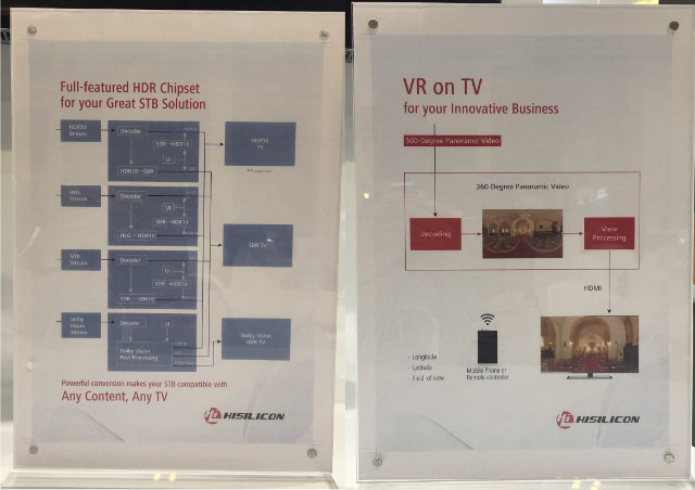
Broadcast Asia international digital multimedia & entertaiment technology exhibition & conference is taking place in Singapore on May 23 – 25, and I’ve been informed that Hisilicon showcased their latest Hi3796M V200 Set-top box SoC with support for 4K DVB, H.265, and high dynamic range technology such as HDR10, HLG and Dolby Vision.

Hiliscon Hi3796M V200 Board and DVB Tuner – Click to Enlarge
Key features and specifications of Hi3796M V200 processor:
- CPU – Quad core ARM Cortex A53
- GPU – ARM Mali-450MP
- Memory – DDR3, DDR3L, DDR4
- Video Output – 1x HDMI 2.0a Tx with HDCP 2.2
- Video format – HEVC, H.264, MPEG2, MPEG4, VC1, VP9, AVS 2.0
- HDR – HDR10, HLG, Dolby Vision, HDR and SDR conversion
- HiVXE 2.0 VPU – Decoder – 4K60 10-bit; Encoder – HEVC/H.264 1080p30 or 2x 720p30
- Ethernet – 1x Gigabit Ethernet, 1x Fast Ethernet
- USB 2.0 – 2x USB 2.0 ports
- SATA & PCIe & USB 3.0 – USB 3.0, SATA 3.0, PCIe 2.0 host interface (optional); cnxsoft’s note: all ports are likely multiplexed, so only one is usable.
- Transport Stream I/F – 2x TS In + 2x TS In or Out + 1x Cable IF in
- SDIO – 2x SDIO 3.0
- Security – Advanced DRM, and CAS (NOCS3.X), and hardware video watermark. TrustZone
The company can provide Android 7.0 and Linux SDKs with middleware and RDK for the processor and development board. HiVXE 2.0 is also said to support PiP and video transcoding. Hardware video watermark ability allows the processor to meet MovieLabs UHD premium service delivery requirements.
Click to Enlarge
It appears the company will also offer a user-friendly way to watch VR videos / 360° videos on the TV by using a mobile app or remote control to navigate in all directions while the video is playing.
I could not find any information at all on the web about Hi3796M V200 processor, so thanks to Ovi for sending pictures directly from the Broadcast Asia exhibition, and allowing us to discover this new multimedia processor.
↧
Intel To Make Thunderbolt 3 Royalty-free, Release Specifications
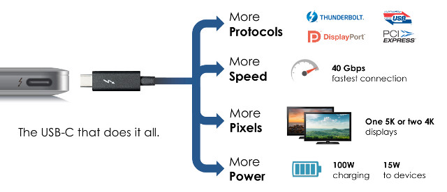
Intel Thunderbolt 3 is a single port connect that supports multiple standards (Thunderbolt, USB 3.1, DisplayPort, PCIe), leverages USB-C connector, and offers up to 40 Gbps throughput. So far, it’s mostly found in higher end computers and laptops, but Intel has now announced plans to make it royalty-free, and “release the specifications to the industry” (so maybe not completely free/public) in order to increase adoption of the standard.
 Thunderbolt-3 main features:
- Thunderbolt, USB, DisplayPort, and power on USB-C
- USB-C connector and cables (small, reversible)
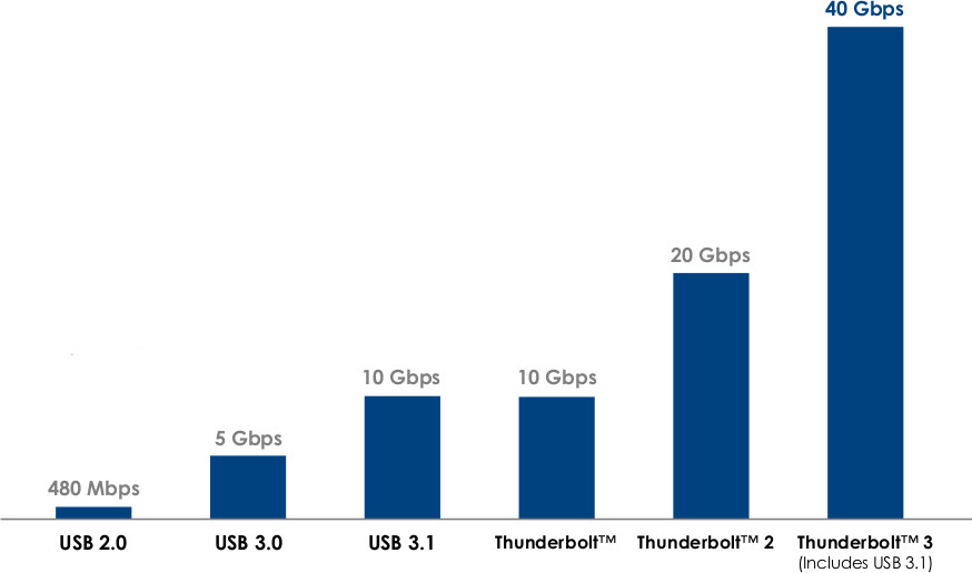
- 40 Gbps Thunderbolt 3 – double the speed of Thunderbolt 2
- Bi-directional, dual-protocol (PCI Express and DisplayPort)
- 4 lanes of PCI Express Gen 3
- 8 lanes of DisplayPort 1.2 (HBR2 and MST)
- Supports two 4K displays (4096 x 2160 30bpp @ 60 Hz)
- USB 3.1 (10 Gbps) – compatible with existing USB devices and cables
- DisplayPort 1.2 – compatible with existing DisplayPort displays, devices, and cables
- Connect DVI, HDMI, and VGA displays via adapters
- Power (based on USB power delivery)
- Up to 100W system charging
- 15W to bus-powered devices
- Thunderbolt Networking
- 10Gb Ethernet connection between computers
- Daisy chaining (up to six devices)
- Lowest latency for PCI Express audio recording
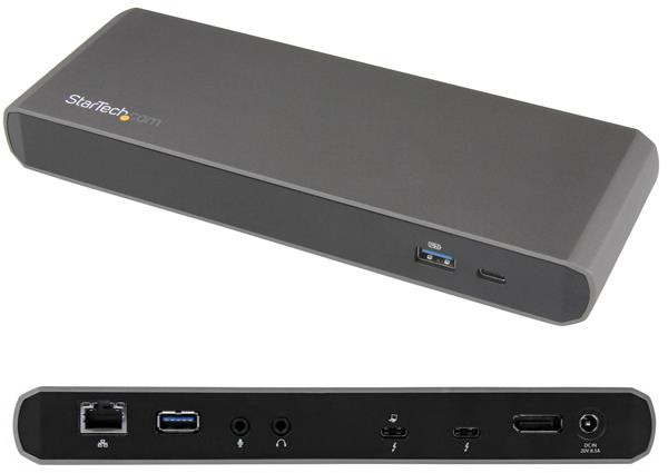
 That means eventually we may get devices with a single Thunderbolt/USB-C like smartphones to connect all peripherals including 4K displays, NVMe SSDs, Ethernet, external GPU, etc.., and power/charge the device though a Thunderbolt 3 dock, which can be purchased for $200 and up. One example is StarTech.com Thunderbolt 3 Docking Station with 4K display, Ethernet, Audio and USB ports going for $199.99 on Amazon US.
Intel also announced plans to integrate Thunderbolt 3 into future Intel CPUs.
↧
Flexible & Adhesive LEGO TAPE Could Be Useful for Makers / DIY Projects
I remember when the Raspberry Pi board first launched, there was no case, and LEGO case designs were popular, and there are certainly various ways you could use LEGO in your projects. But I’ve just discovered LEGO tape that could bring much more flexibility to your design.
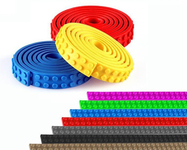
It’s just like LEGO, but flexible, and with an adhesive flat side, so you can cut it to any size you want, and stick it anywhere. “Back to Realitee” shop sells those for $12.95 for 1 meter tapes. available in various colors. This allows kids to play differently with LEGO by sticking to wall, or making special shapes.
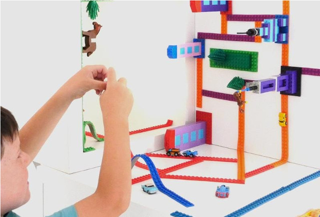 If times are stuff, and you’d like to spend less, Aliexpress has similar LEGO tapes, with the cheaper ones without a sticky side, so you’d have to use you own double sided sticky tape. Prices start at $0.89 shipped for 25cm, and $3.79 for 1 meter (4x 25 cm). If you want one meter with a 3M sticky side, price goes up to around $10 shipped for one meter or maybe two meters, as Aliexpress makes it unclear.
Via Karim Yaghmour
↧
↧
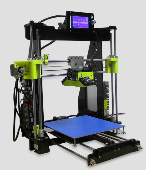
Raiscube Prusa I3 3D Printer Review – Part 1: Assembly, First Prints, and Configuration
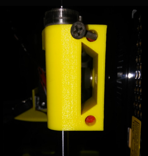
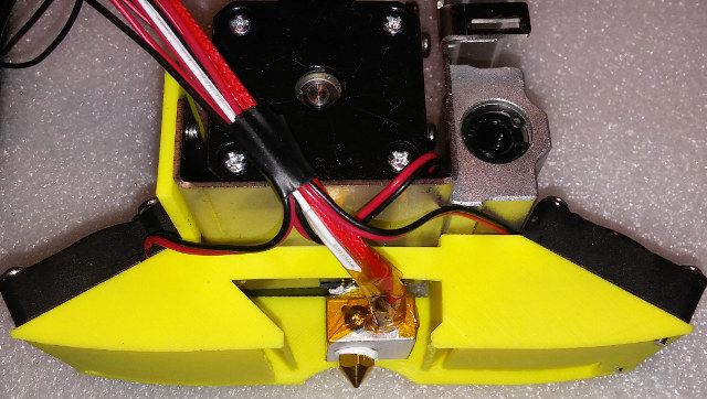
Karl here. Today we are going to start looking a Raiscube Prusa I3 3D printer kit sent for review by GearBest. It’s very similar to most low cost 3D printer kits with one exception. The parts cooler is not like any similar kits that I have seen. In my short time researching these kits the parts cooler is one of the first upgrades I see people do. Typically the parts coolers are inadequate or nonexistent. We will find out that it is actually too good. In this review we are first going to outline the basic components and a mini build guide. Then we will look and see how it prints.
Prusa I3 Desktop LCD 3D Printer Specs
 Main Features:
- Mainboard: Melzi V2.0
- 210 x 210 x 210mm build volume
- 12864 LCD screen shows your printing information directly and easy for you to manipulate
- 8mm-thick laser cut acrylic frame for rigidity and long life
- 3 cooling fans, strong air flow to enhance cooling performance
- Hot bed temperature up to 120 Deg.C, great for ABS material
- Click here to know the installation details
Specification:
- Main board: Melzi V2.0
- Build volume: 210 x 210 x 210mm
- Filament diameter: 1.75mm
- Z axis precision: 0.004mm, XY axis precision: 0.012mm
- Printing precision: 0.1 – 0.2mm
- Layer thickness: 0.1 – 0.4mm
- Nozzle diameter: 0.4mm
- Extruder temperature: 260 Deg.C ( max. )
- Hot bed temperature: 120 Deg.C ( max. )
- Printing format: STL, OBJ, G-code
- Support system: Windows XP, Win7, Win 8, Linux, Mac
- Support language: English, Chinese
- The color of the 0.5kg PLA material we send is sent at random
3D Printer Basics
When putting a kit printer together it is really good to understand the basics on how they operate and the basic components. At the most fundamental level, plastic is heated up to a point where it is molten. Layer by layer, from the bottom up, the printer lays down the plastic to form the object. There are 3 directions X (left and right), Y (forward and back) and Z (up and down).
The basic motion pieces are:
- Stepper motors
- End stops
- Rods
- Belts
- Bearings
- Frame
- Hot end (This is melting chamber, cooling fans, etc)
- Build plate
On this style printer the hot end and nozzle ride on 2 rods in the X direction. It is moved right and left by a belt that runs between a stepper motor with gears on the shaft and a bearing on the opposite side. On the top X rod is an end stop. End stops are used so the printer knows where in a 3 dimensional space the end of the nozzle is. When a printer is first turned on, it doesn’t know exactly where the nozzle is. The home process that is ran before every print, gives the printer a point of reference for all axis. The Y axis is very similar to the X axis. Instead of the hot end the build plate moves from the front to the back. Again the stepper motor in the back moves the plate forward and back with a belt, gears, and a bearing. Finally the Z axis is controlled by 2 stepper motors that work together to move the hot end up and down. It is guided by 2 rods but instead of a belt a threaded rod turns to move the hot end up and down.
At this point we can move our 3 directions X,Y, and Z. X and Y move with belts. Z moves with a threaded rod. Precision is the name of the game with 3D printers. Everything needs to be tight and not sloppy.
Before Starting to Print
Before you even turn the machine on be sure to move all your axis, and make sure nothing binds or rubs and everything is tight.
- The belts must be tight in order to not slip during fast moves. Make sure it isn’t rubbing anything so check alignment visually.
- Special consideration has to be made for the Z axis because 2 stepper motors have to work together. The X axis has to be parallel with the build plate. I have read using a ruler but I just used my glue stick to get set. I place the gluestick between stepper motor and Z rod bracket and set height on both sides.
- Place the 3 end stops close to the correct positions. Move your axis by hand and make sure the x is at the left edge of the build plate. The Y axis puts the hot end at the front of the build plate. And the Z axis is just above slightly above the build plate.
- Check to make sure none of the wires get in a bind especially the build plate and X stepper motor.
During this process I found that my rods that the X axis slid on seemed too short. I contacted GearBest and they were correct. During assembly I initially put the wrong length rods in and tried to force so I might have damaged something. I ended up having to make some spacers about 22mm long to make up the difference. This was completely my fault. I didn’t pay attention enough to the rod lengths in the instructions. I initially cut some bolts but eventually just printed some slightly longer and trimmed them to take up the slack. My trim job on red slugs wasn’t perfect so I wedged a drywall screw a couple treads and has worked well since. As an afterthought I might have been able to do without the red filler pieces and used screws from the beginning.
After turning on navigate the menus and preheat for PLA, load the filament, and home the nozzle. Use the menus, and move the nozzle all around on all axis and extrude some filament. I had to adjust the potentiometer on the stepper motor drivers on both the Z and extruder up. The stepper motors weren’t getting enough juice, and they were clicking and not moving. If you hear clicking that is likely the cause or maybe a binding issue.
Now we need to level the bed. I never printed directly on the bed. I cut a piece of glass that I had that was leftover from CR-10 review. The glass came in a 6 pack of 12” squares for about $10. I had such good luck I went directly to it. Glass is nearly perfectly flat. If it wasn’t you would see these variances in the reflection. I have a tile cutter from where I tiled my bathrooms and used it to cut the mirror down to size. Home the printer again then disable the stepper motors. In the CR-10 review I found leveling by eye was the best but because of the huge cooling fans I wasn’t able to get the right angle. I took a different approach this time. I moved to each corner and just barely tapped the build plate up until I couldn’t hear the glass tapping the nozzle.Then I backed it up just to hear it tapping again. I went around the 4 corners 4 or 5 times to get it adjusted.
Building Prusa i3
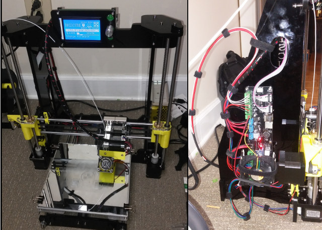
I had about 10-11 hours with building, troubleshooting, and managing the wires. I read people doing these kits in about 8 hours but I don’t see how unless they didn’t manage wires. I recommend velcro and not zipties. I think it looks much neater and you can adjust without fear of cutting tiny wires. I downloaded instructions from GearBest page. I found them adequate but not great. All the necessary tools were included with the exception of a pliers or wrench to tighten the big bolts. It came with some cool looking green pla. Below are some of the more notable components. There is no settings with this kit nor software. It does come with an 8 GB SD card but it is blank. I did end up with spare nuts and bolts which is nice.
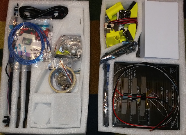
Kit in package – Click to Enlarge

RepRap Melzi v2.0 Board – Click to Enlarge
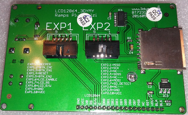
LCD Board – Click to Enlarge
Some Cable Management – Click to Enlarge
I made just a couple changes to the stock build. I already mentioned that I installed a mirror for the build plate. I also added a fan to keep the board cool. The stepper motor drivers seemed really hot so I added the fan to keep them cool. When I first found out about reviewing this printer I thought ohh boy I was going to have to do a lot of mods. Adding a MOSFET, bracing etc… to make it print well. I am glad I didn’t buy the MOSFET ahead of time because I don’t think it is needed. A MOSFET is used to to take the burden of supplying power to heat the bed from the board and pull it directly from the power supply. There have been cases of really cheap boards/connectors causing fires.
The instructions show setting up the Z axis stepper motors in some series way but I couldn’t get it to work. I did some research and found out you can also run them parallel and I connected them this way.
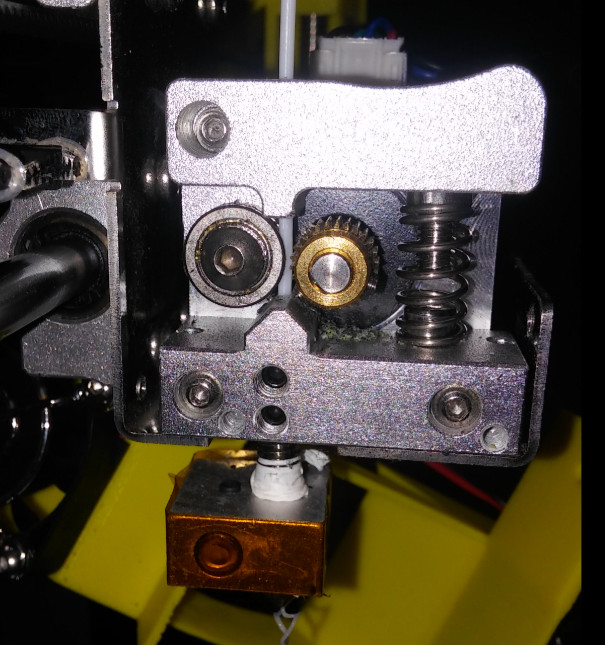
I got 1 jam so I took a picture while the fan was off. I tried to print the cat that came with the CR-10, and it has big retractions in it. I believe it pulled back too far too many times and pulled molten filament and it got in the gears. Very simple design.
 Final build pictures below.
Click to Enlarge
First Print
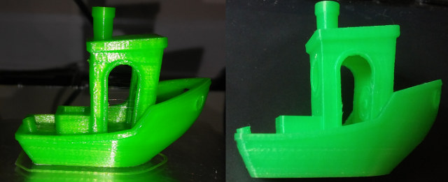
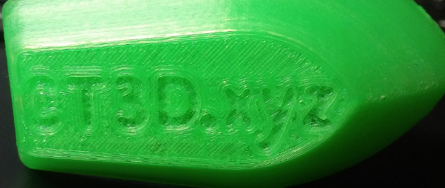
The printer did not come with any pre-sliced files with it. So I opted for a print I have printed several times and knew. I just guessed on temperature and it turned out good. I hate to take these pictures with flash but I didn’t have choice with the lighting while it was on the bed. The picture without the flash is more indicative of what this filament looks like in person. The benchy looks like it missed a layer on the hull but it feels smooth.
Click to Enlarge
With this translucent filament I found I needed more top and bottom layers and my initial print was too hot and caused stringing.(Nope too cool)
Craftware, Octoprint, and dialing in settings
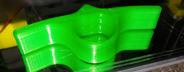
I use Craftware to slice my objects for printing. I started out with the settings that I dialed previously for CR-10 review. Which was basically stock settings with some slight tweaks. After printing and testing, I found that the fan needs to be set to 75% or less or it cools too well, and causes some curling in extreme overhangs. One reviewer of the printer on GearBest thankfully mentioned this or I might not have tried this. While troubleshooting, I could not override the fan settings with the menu during testing. I would set the fan slower, then a short while later it was back at the percentage I set in the slicer. I looked at the gcode and at every layer change I see an M106. M106 is the gcode to change fan speed. Gcode is the language for 3D printers, CNC machines, and laser engravers are programmed with. In the future I will remove all of these, when wanting to test on the fly. I tested with Cura, and it is set only once at the beginning so it should not be an issue. Another odd thing is that I found that the green filament strings more at lower temperatures.
Octoprint worked as expected at 250,000 baud rate. Octoprint allows you to start stop prints through a web page, do time lapse videos, etc…
If you would like more info on Octoprint or Craftware, check the second part of CR-10 review. Here are the presets that I used for the green PLA that came with the printer for Craftware.
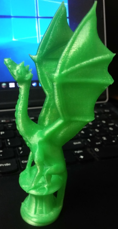
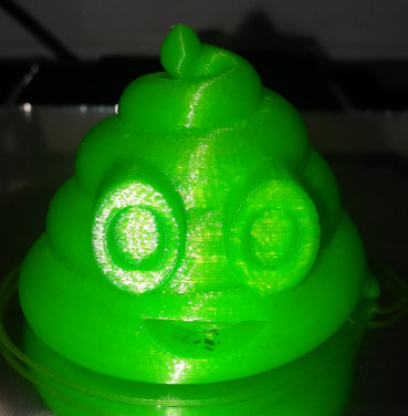
All of the prints below are printed at suboptimal temperature and fan speed and still turned out well. The lattice cube was the only one with fan and temperature calibrated.
Click to Enlarge
Click to Enlarge
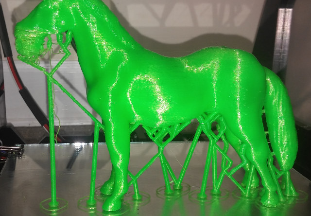
- Unicorn first failed print. I added some additional custom supports to the head in Craftware and it printed fine. Didn’t get a picture of final before daughter gave to friend. I was very surprised all these little supports made it but one. https://www.thingiverse.com/thing:182335
Click to Enlarge
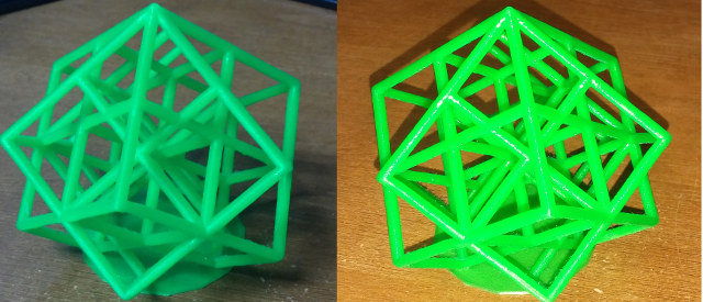
- CR-10 left vs Prusa I3 right. I broke part off CR-10. More stringing but I think with retraction and temp calibration I can dial in. The CR-10 is just slightly better. This was printer before I figured out to turn the fan down – https://www.thingiverse.com/thing:127683
Click to Enlarge
Click to Enlarge
Final Thoughts
Good
- The bed and the nozzle heat up fast
- Relatively quiet
- Prints accurately
- No modifications needed to print well. Only one recommendation is a mirror print plate.
- All the bearings and parts are tight and not sloppy.
- Wiring is properly sized for the loads.
Not so good
- Needs better instructions. Might not be easiest to put together for a beginner.
- Better springs for build plate and thicker build plate H bracket. (I have to re-level every print. I think this would help)
- Beeper/buzzer is too loud so I removed it.
- Add fan to keep Arduino board cool.
I like this printer and had good success with it. There are just a few minor gripes. I was apprehensive over the acrylic but it serves its purpose to keep costs down. I’m relatively new to 3D printing but I believe this is a good kit. The parts cooling fan is fantastic. I am currently printing a baby groot in kcamel wood PLA that I purchased from GearBest. I will include more prints in 2nd part. In the second part we will also look to see if adding an E3D clone improves quality.
I would like to thank Gearbest for the Prusa I3 clone for review, and if interested, you can purchase it for $179.9 including free worldwide shipping using CNXPrusa coupon.
↧
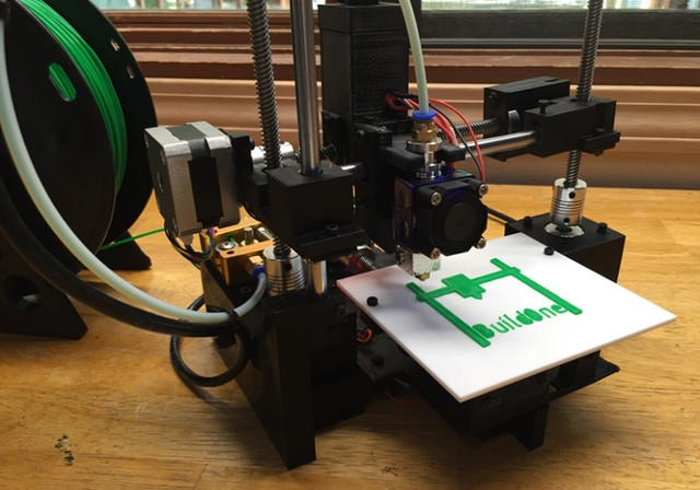
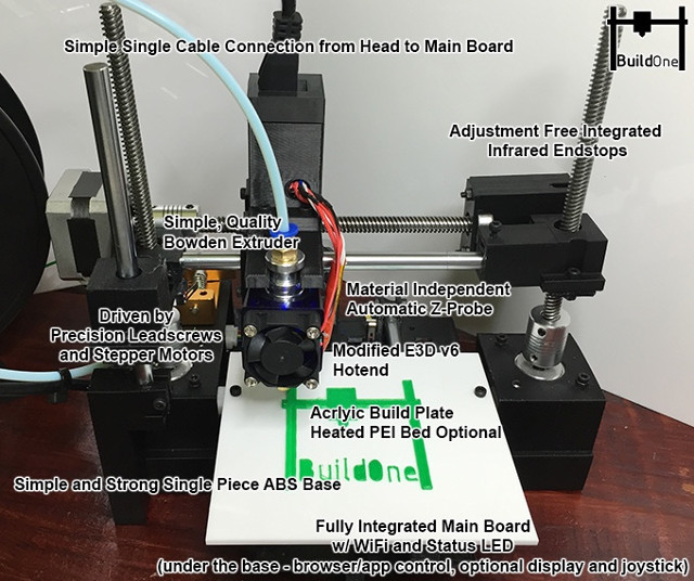
BuildOne is a $99 WiFi 3D printer with Auto Bed-Leveling (Crowdfunding)
3D printers have become more and more affordable with products like Anet A8 3D printer that sells for a little over $150, and now many models are below $200, such as the Prusa i3 clone just reviewed by Karl. But BuildOne is going a step further by bringing the price right below $100, at least during the Kickstarter campaign, and the basic model.
 BuildOne 3D printer specifications and key features:
- Print volume – 125 x 125 x 125 mm
- Minimum layer resolution – 50 microns (100 to 300 recommended for most prints)
- Horizontal position resolution – 20 microns / 0.02 mm
- Filament size – 1.75 mm
- Filament type – PLA (ABS, nylon, and more with heated bed)
- Notable features – Auto-calibration, auto leveling, LED status, panic button to interrupt prints, modularity with easy to replace parts and optional add-ons
- Connectivity – WiFi to print from web browser or smartphone
- Power Supply – 12V
- Dimensions – fits inside a 200m cube
- Weight – About 2 kgs
The 3D printer uses a modified version of the Marlin firmware with the ability to have the head unit communicate via I2C to reduce the wiring required and allow for future upgrades. That’s also mean you’ll be able to modify the 3D printer source code if you wish to do so. The printer is compatible with most sliders and interfaces sch as Slic3r, Cura, Craftware, etc…, and can also optionally connect to a cloud service, so you could print from anywhere, as long as your print is online.
 Four models are available:
- BuildOne Basic Edition ($99)
- BuildOne Plus Edition ($114) with extra PEI build plate
- BuildOne Deluxe Edition ($149) ABS ready, with display upgrade, PEI build plate, and heated bed
- BuildOne Ultimate Edition ($174) based on Deluxe Edition plus a full enclosure and carrying case
You can also pledge for upgrades independently:
- $35 for heated PEI bed
- $15 for display upgrade with OLED display, tactile joystick
- $30 for full enclosure and carrying case
- $15 for premium PLA filament spool
Robotic Industries LLC, the startup behind the project, aimed to reach $100,000, and they’ve already done that with 27 days to go. Shipping adds $20 to $25 for the basic edition, and goes up if you add more options (up to $30 to $45). Delivery is scheduled for September 2017, so it’s look like they are basically done with development, and are just getting funds for mass production. Some crowdfunding campaigns fail, and the number of failures appear to be even greater for 3D printer projects (actually an unrelated $100 3D printer KS project was a scam), but Robotic Industries LLC claims to have a proven and experienced team, as well as industry partners such as Digistump, and Rigao electronics. Their website currently contained a picture with a link to Kickstarter.
↧
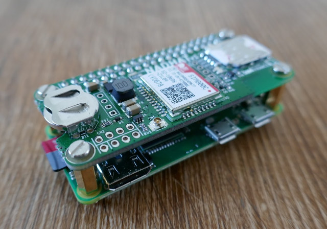
Nadhat is an Add-on Board for Raspberry Pi Boards with 2G GSM/GPRS Support
Making Raspberry Pi HATs for fun seems to have become a popular hobby, as after checking out Leon Anavi’s Infrared pHAT a little while ago, I’ve just come across Nadhat add-on board with GSM/GPRS and Bluetooth 3.0 made by Frederic Pierson in his spare time.
Click to Enlarge
Nad stands for “Network Access Device”, and the device comes with the following specifications:
- SIM800C module with 2G GSM/GPRS support, and Bluetooth 3.0 + EDR (but Bluetooth is not mentioned by the developer, so it may not work right now)
- SIM card slot + connector for GSM antenna
- CR1225 cell battery slot for RTC
- 40-pin header provided, but not soldered
- Dimensions – 65 x30 mm, compatible with Raspberry Pi Zero
He explains that he made the board himself and the PCBs “are leaded reflow processed and do not follow regulations in Europe”. You’ll also have to provide your own GSM antenna and CR1225 battery. He’s released some files on github, the datasheet for the components, the schematics – but in PDF only, why? – , and the software directory only contains a short script to power up SIM800C.
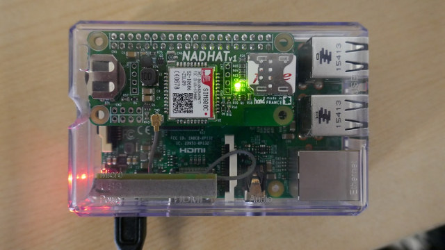
Raspberry Pi 3 with Nadhat board – Click to Enlarge
The cellular module is attached to the Pi via /dev/ttyAMA0 serial interface, and you’ll have to send AT commands to control it. He also checked out 3G and 4G support as some people asked possible due to 2G sunset, but the modules he found where both expensive, and much bigger than the 2G modules, making it impossible to fit into the RPi Zero form factor.
Since the board is just a hobby project, it will probably never be manufactured in large quantities, but Frederic made a few boards himself, which you can get for 49 Euros + delivery if you are interested, and boards are still available.
↧
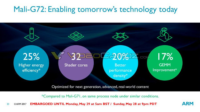
ARM Cortex-A75 & Cortex-A55 Cores, and Mali-G72 GPU Details Revealed
We’ve already seen ARM Cortex A75 cores were coming thanks to leak showing Snapdragon 845 SoC will feature custom Cortex A75 cores, but we did not have many details. But since we live in a world where “to leak is glorious”, we already have some slides originally leaked through VideoCardz with the post now deleted, but Liliputing & TheAndroidSoul got some of the slides before deletion, so let’s see what we’ve got here.
ARM Cortex A75
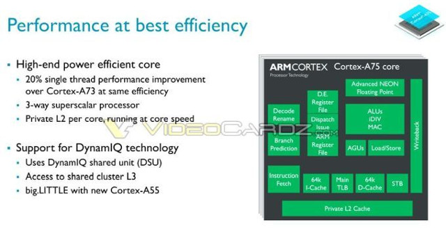 So ARM Cortex-A75 will be about 20% faster than Cortex A73 for single thread operation, itself already 30% faster than Cortex A72. It will also be the first DynamIQ capable processor together with Cortex A55 with both cores potentially used in big.LITTLE configuration.
 Cortex A75 performance is only better for peak performance, and remain the same as Cortex-A73 for sustained performance.
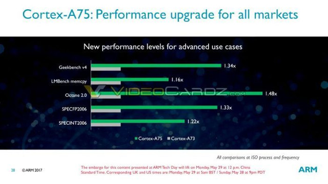 The chart above does not start at zero, so it appear as though there are massive performance increases, but looks at the number and we can see 1.34x higher score with GeekBench, and 1.48x with Octane 2.0. Other benchmarks also have higher scores but between 1.16 and 1.33 times higher.

Click to Enlarge
Cortex A75 cores will be manufactured using 10nm process technology, and clocked at up to 3.0 GHz. While (peak) performance will be higher than Cortex A73, efficiency will remain the same.
ARM Cortex A55

Click to Enlarge
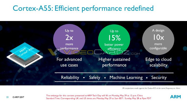
ARM Cortex A55 is the successor if Cortex-A53 with about twice the performance, and support for up to eight cores in a single cluster. There are octa-core (and even 24-core) ARM Cortex A53 processor but they also use multiple 4-core clusters.
Click to Enlarge
Power efficiency is 15% better too, and ARM claims it is 10x more configurable probably because of DynamIQ & 8-core cluster support.
Click to Enlarge
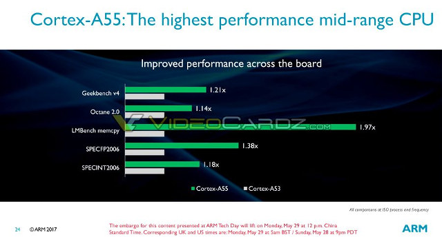
If we have a closer look at the benchmarks released by the company, we can see the 2x performance increase is only valid with LMBench memcpy memory benchmark, with other benchmarks from GeekBench v4 to SPECINT2006 showing 1.14x to 1.38x better performance. So Integer performance appears to be only slightly better, floating point gets close to 40%, and the most noticeable improvement is with memory bandwidth.
ARM Mali-G72 GPU

Click to Enlarge
Mali-G72 will offer 1.4x performance improvement over 2017 devices, which must be Mali-G71…, and will allow for machine learning directly on the device instead of having to rely on the cloud, better games, and an improved mobile VR experience.
Click to Enlarge
The new GPU is also 25& more efficient, and supports up to 32 shader cores. GEMM (general matrix multiplication) – used for example in machine learning algorithms – is improved by 17% over Cortex A73.

Click to Enlarge
Based on the information we’ve got from Qualcomm Snapdragon 845 leak, devices based on ARM Cortex A75/A55 processor and Mali-G72 GPU should start selling in Q1 2018. We may learn a few more details on Monday, once the embargo is lifted.
↧
↧
FriendlyELEC Mailbag: NanoPi NEO OLED Starter Kit, NEO Station NS-120B, and NanoPi K2 Multimedia Kit
FriendlyELEC will send me some review samples from time to time, and normally I just ask for one item, but they aways send a bunch of their products instead. This time I asked for a NanoPi NEO NAS Kit v1.2 to play with, but I got clearly more than what I asked for…
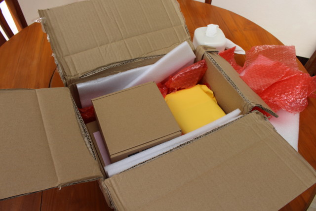 Let’s start with the box at the top.
Click to Enlarge
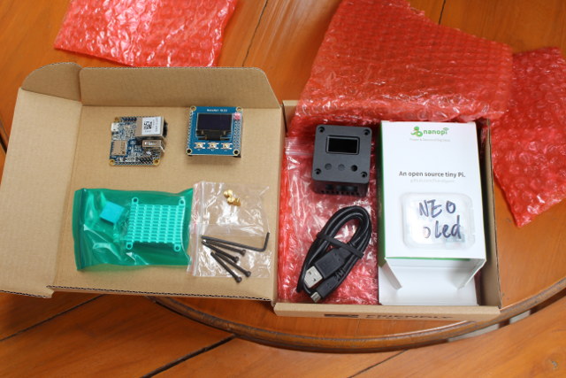
It contains “NanoPi NEO complete starter kit” selling for $29.99for $29.00 with the following items:
- NanoPi NEO board
- NanoHat OLED
- Heatsink and thermal pad kit
- Akuminum housing
- a Mico USB cable
- A micro SD card pre-loaded with NEO OLED Ubuntu firmware.
- Three buttons, and screws
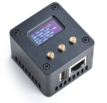
It’s actually not fully complete, as you’d need to provide and solder your own male headers to NanoPi NEO board. I did not have time for soldering that day, but the final results should be really neat based on pictures from their website.
 If you prefer the more powerful board, the same kit is sold with NanoPi NEO2 board for $34.00. Both kits are currently out of the stock, but so you may want to add the one you like to your wish list.
Moving to those very thick yellow / orange envelopes…
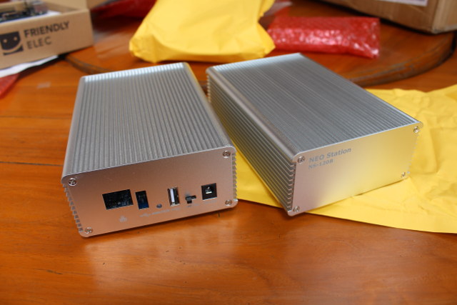
Click to Enlarge
That’s two NanoPi NEO NAS kits v1.2, with the marking showing “NEO Station NS-120B”, maybe in reference to “Synology DiskStation”, but they don’t use that name in their website, which is probably a good idea. The models I received as the side plate for NanoPi NEO 2 board, but there may be more inside. I’ll check it later, since I’ll review the kit in details in a separate post.
Next up is a box with “K2” written on it.
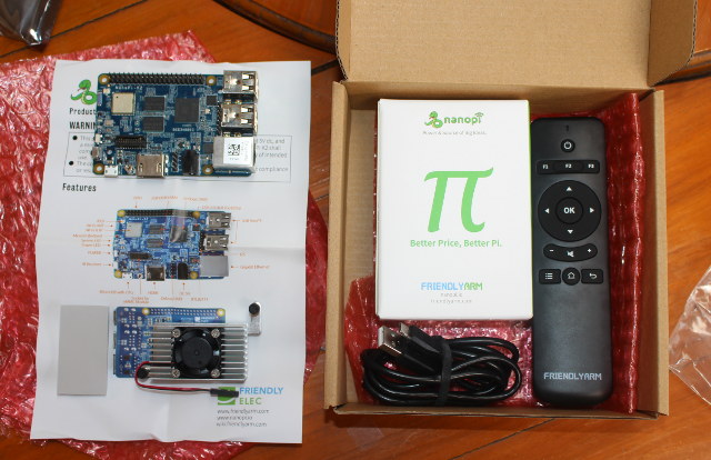
Click to Enlarge
Unsurprisingly NanoPi K2 board powered by Amlogic S905 processor can be found inside. But we also have a heatsink +fan + thermal kit, a micro USB cable, and an IR remote control. Almost all you need for a TV box, but looking further into the big package, we’ll find an acrylic enclosure completing the kit.
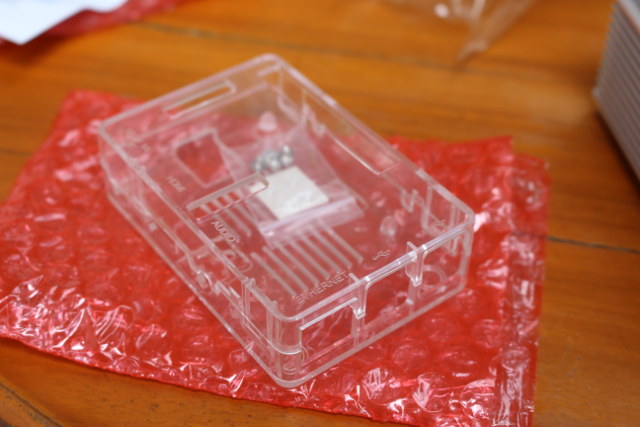
Click to Enlarge
I’ve also taken closer pictures of the K2 board since it’s the first time I’ve received it.
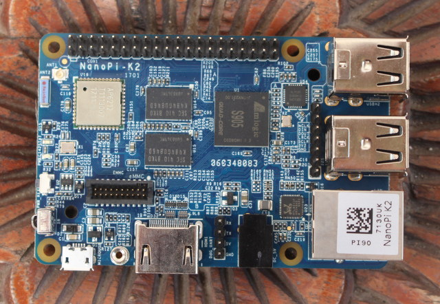
Click to Enlarge
The board has basically the same form factor and ports as the Raspberry Pi 3, but it adds an IR receiver, more memory (2GB), Gigabit Ethernet, and a slot for eMMC modules – which are yet to be available -, but lacks MIPI CSI and DSI connectors. It should be noted however, that while FriendlyELEC mentioned both Linux and Android, they appear to focus their efforts on Android only, with no actual plans to release a Debian / Ubuntu image:
The bad news, according the the Moderator of the FriendlyArm forum, there are no plans for a debian image. Only the supplied Android 5.1 image. 🙁 Meaning its get out the uboot and the compiler and make your own with a bit of USB TTL flashing to boot.
So any Linux images would have to be done & maintained by the community.

Click to Enlarge
NanoPi K2 board goes for $39.99, but the complete multimedia kit should cost more. The problem is that I can’t find it on their website, but if we adds individual item, namely the heatsink + fan ($5.99), RC-100 IR Controller ($2.99), micro USB cable ($1.97), and the acrylic enclosure ($1.99) to total adds up to $52.93 + shipping, which costs a little more than a TV box with similar specifications, but provides more flexibility due to the source code available for NanoPi K2.
I had two more boxes in the package with one more K2 multimedia kit and an extra acrylic enclosure, which would make a nice candidate for a future giveaway week.
↧
Intel Compute Card Apollo Lake and Kaby Lake SKUs, Block Diagrams, and (Partial) Specifications
Intel Compute cards are the latest ultra-thin CPU cards introduced by Intel at the beginning of the year, with a concept similar to EOMA68 CPU cards, that it to allow CPU card upgrades or replacements, and interoperability across compatible devices such as smart kiosks, IoT gateways, and so on. But at the time, Intel did not reveal that many details about the different cards, although we know NexDock is working on laptop dock compatible with Intel Compute Cards. But I’ve recently received some block diagrams for Apollo Lake Pentium/Celeron, and Kaby Lake Core M/Core i5 compute cards.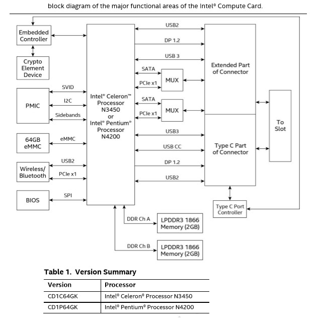 There will two SKUs for Apollo Lake compute cards sharing the same specifications, except for the processor:
- SoC
- CD1C64GK SKU – Intel Celeron N3450 quad core processor @ 1.1 / 2.2 GHz (base/turbo) with 12EU Intel HD Graphics Gen9; 7.5W TDP
- CD1P64GK SKU – Intel Pentium N4200 quad core processor @ 1.1 / 2.5 GHz with 18 EU Intel Gen9 HD graphics; 6W TDP
- System Memory – 4GB dual channel LPDDR3-1866
- Storage – 64 eMMC flash, SPI flash for BIOS
- Connectivity – WiFi and Bluetooth module connected via USB or PCIe
- Compute Card connector:
- USB type C part with USB 3.x, USB CC (Configuration Channel), DisplayPort 1.2 and USB 2.0 signals
- Extended part with USB 2.0, DisplayPort 1.2, USB 3.x, 2x multiplexed SATA & PCIe x1 interfaces
- Others – PMIC, Embedded Controller, and Crypto Element Device
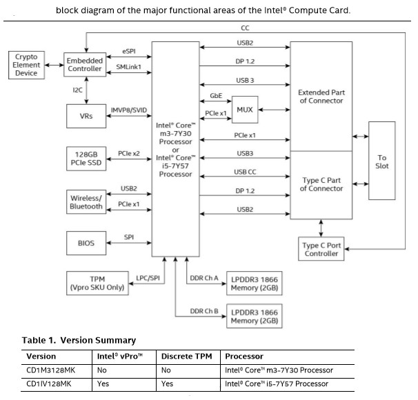 There will also be two more powerful and expensive Kabe Lake compute card with the following specifications:
- SoC
- CD1M3128MK SKU – Intel Core m3-7Y30 dual core / quad thread processor @ 1.0 / 2.6 GHz (base/turbo) with Intel HD Graphics 615; 4.5W TDP
- CD1IV128MK SKU – Intel Core i5-7Y57 dual core / quad thread processor @ 1.2 / 3.3 GHz with Intel HD Graphics 615; 4.5W TDP; Support Intel vPro
- System Memory – 4GB dual channel LPDDR3-1866
- Storage – 128GB PCIe SSD, SPI flash for BIOS
- Connectivity – WiFi and Bluetooth module connected via USB or PCIe
- Compute Card connector:
- USB type C part with USB 3.x, USB CC (Configuration Channel), DisplayPort 1.2 and USB 2.0 signals
- Extended part with USB 2.0, DisplayPort 1.2, USB 3.x, 1x multiplex Gigabit Ethernet / PCIe x1, and 1x PCIe x1
- Others – Voltage regulators (VRs), Embedded Controller, and Crypto Element Device; CD1IV128MK only: TPM
I was not aware of any Core i5 processors with such a low TDP, which can also be tuned up to 7W, and down to just 3.5W. The processor was just launched in January, a few devices are equipped with the processor, but I still managed to find Lenovo ThinkPad X1 Tablet 20JB ( $1,450), as well as some benchmarks for reference.
↧
Intel DLIA is a PCIe Card Powered by Aria 10 FPGA for Deep Learning Applications
Intel has just launched their DLIA (Deep Learning Inference Accelerator) PCIe card powered by Intel Aria 10 FPGA, aiming at accelerating CNN (convolutional neural network) workloads such as image recognition and more, and lowering power consumption.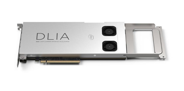
Some of Intel DLIA hardware specifications:
- FPGA – Intel (previously Altera) Aria 10 FPGA @ 275 MHz delivering up to 1.5 TFLOPS
- System Memory – 2 banks 4G 64-bit DDR4
- PCIe – Gen3 x16 host interface; x8 electrical; x16 power & mechanical
- Form Factor – Full-length, full-height, single wide PCIe card
- Operating Temperature – 0 to 85 °C
- TDP – 50-75Watts hence the two cooling fans
The card is supported in CentOS 7.2, and relies on Intel Caffe framework, Math Kernel library for Deep Neural Networks (MKL-DNN), and works with various network topologies (AlexNet, GoogleNet, CaffeNet, LeNet, VGG-16, SqueezeNet…). The FPGA is pre-programmed with Intel Deep Learning Accelerator IP (DLA IP).
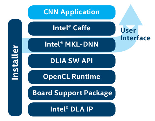 Intel DLIA can be used by cloud services providers to filter content, track product photos, for surveillance and security applications for example for face recognition and license plate detection, in the factory to detect defects automatically, and in retail stores to track foot traffic, and monitor inventory.
You’ll find more details including links to get started and the SDK in the product page.
↧
STMicro Unveils STM32L4 Discovery Kit for IoT with WiFi, BLE, NFC, Sub-GHz RF, and Plenty of Sensors
STMicro has recently introduced B-L475E-IOT01A Discovery kit powered by STM32L4 Cortex-M4 and targeting IoT nodes with a choice of connectivity options including WiFi, Bluetooth LE, NFC, and sub-GHZ RF at 868 or 915 MHz, as well as a long list of various environmental sensors.
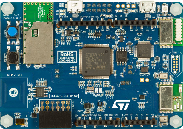
Click to Enlarge
B-L475E-IOT01A Discovery kit key features and specifications:
- MCU – STM32L4 Series MCU based on ARM Cortex -M4 core with 1 MB Flash memory, 128 KB SRAM
- Storage – 64 Mbit (8MB) Quad-SPI Flash memory (Macronix)
- Connectivity
- Bluetooth 4.1 LE module (SPBTLE-RF)
- Sub-GHz (868 or 915 MHz) low-power-programmable RF module (SPSGRF-868 or SPSGRF-915)
- Wi-Fi module based on Inventek ISM43362-M3G-L44 (802.11 b/g/n compliant)
- Dynamic NFC tag based on M24SR with its printed NFC antenna
- Sensors
- 2x digital omni-directional microphones (MP34DT01)
- Capacitive digital sensor for relative humidity and temperature (HTS221)
- 3-axis magnetometer (LIS3MDL)
- 3D accelerometer and 3D gyroscope (LSM6DSL)
- 260-1260 hPa absolute digital output barometer (LPS22HB)
- Time-of-Flight and gesture-detection sensor (VL53L0X)
- USB – 1x micro USB OTG port (Full speed)
- Expansion – Arduino UNO V3 headers, PMOD header
- Debugging – On-board ST-LINK/V2-1 debugger/programmer with USB re-enumeration capability: mass storage, virtual COM port and debug port
- Misc – 2 push-buttons (user and reset)
- Power Supply – 5V via ST LINK USB VBUS or external sources
The board supports ARM mbed online compiler, but can also be programmed using IDEs such as IAR, Keil, and GCC-based IDEs. STMicro also provides HAL libraries and code samples as part of the STM32Cube Package, as well as X-CUBE-AWS expansion software to connect to the Amazon Web Services (AWS) IoT platform.
You’ll find documentation, hardware design files, software, and tools on the product page, where you’ll also be able to purchase the board for $51.94 with either a 868 or 915 MHz RF module.
↧
↧
Banana Pi BPI-M2 Berry Allwinner V40 Development Board, Allwinner Business Units & SDK/Software Management
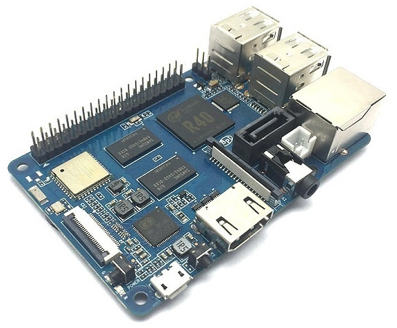
SinoVoIP has unveiled yet another new board with Banana Pi BPI-M2 Berry this week-end. It’s actually quite similar to Banana Pi BPI-M2 Ultra board, by they replaced Allwinner R40 with Allwinner V40 processor, removed some features, and use Raspberry Pi 3 form factor. If we look at Allwinner V40 product brief we can see the specifications look almost identical, with V40 potentially exposing an extra CAN bus. The company’s announcement was very confusing since they show Banana Pi BPI-M2 Berry board with Allwinner R40 instead of Allwinner V40.
 Banana Pi BPI-M2 Berry specifications:
- SoC – Allwinner V40 quad Core ARM Cortex A7 processor with ARM Mali-400MP2 GPU
- System Memory – 1G DDR3 SDRAM
- Storage – micro SD slot, SATA interface
- Connectivity – 1x Gigabit Ethernet port, 802.11 b/g/n WiFi and Bluetooth 4.0 (AP6212 module)
- Video Output – HDMI 1.4 port up to 1080p60, 4-lane MIPI DSI display connector
- Audio I/O – HDMI, 3.5mm headphone jack, built-in microphone
- USB – 4x USB 2.0 host ports, 1x micro USB OTG port
- Camera – CSI camera connector
- Expansion – 40-pin Raspberry Pi compatible header with GPIOs, I2C, SPI, UART, ID EEPROM, 5V, 3.3V, GND signals.
- Debugging – 3-pin UART for serial console
- Misc – Reset, power, and u-boot buttons
- Power Supply – 5V via micro USB port; AXP221s PMIC
- Dimensions – 85mm x 56mm
The Wiki is also shared for BPI-M 2 Ultra/Berry boards. The company also showed a picture of BPI-M2 Ultra with Allwinner V40 confirming both processors are pin-to-pin-compatible.
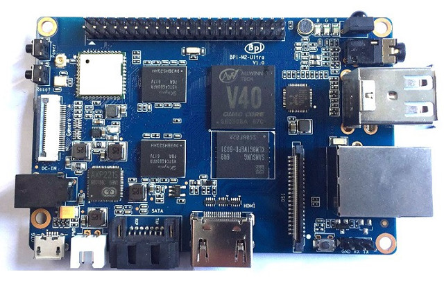
BPI-M2 Ultra Board with Allwinner V40 Processor
So why bother doing different processors since they are so similar? Last time, we were told Allwinner A64 and R18 had different SDKs, so it should be the same for R40 and V40. Allwinner has different family of processors dedicated to different market segments: A-series are application processors, H-series are for home entertainment, R-series for the IoT, and V-Series for video camera applications. In some ways, it makes sense to have different business units that specialize in specific market segments. If you customer wants to make an action camera redirect him to the V-series guys, a TV box that’s for H-series, and so on.
There’s been a long-ish discussion about Allwinner business units on CNX Software. What has apparently been happening is that some processors can be used across market segments, so they have duplicates (or close to it) with for example Allwinner A64/R18 that’s just the same chip but assigned to a different business unit. Each business unit work and release their own SDK, and based on different Linux and Android version for different SDK, there does not seem common work across business units, and they appear to have separate software teams. The processors are differentiated by “CHIP ID”, and by default you can’t run firmware generated by R18 SDK on A64, and vice-versa, since the bootloader will detect the ID and prevent the software to run. That also looks like a bad idea, since for example a software bug fixed on Allwinner R18 SDK, may go unnoticed on Allwinner A64 for years etc… So ideally all business units should get their software from a single team taking care of low level software (bootloader/kernel/drivers), middleware (Android/rootfs), while software developers’ part of a given business unit may work on the market specific software.
Jon had more insights on this business organization:
The R group is releasing a different SDK for the R18. They are not using the A64 one. That strongly suggests to me two sets of software people. A single software group would have simply added the R18 extras into the A64 SDK.
You want a centralized Linux and Android group. Then inside that group you develop specialists. For example the DMA person, the UART person, the Ethernet person, etc. That person is responsible for driver support over all of the CPUs Allwinner makes. They become experts on this piece of the SOC. The output of this group is a single SDK that supports all Allwinner processors. Like what mainline Linux is doing for Allwinner SOC currently. Not the single CPU kernels that AW keeps releasing.
Then you can give this central software group two instructions:
1) Add a new SOC to the existing base. Each specialist will extend their existing driver to add support for the new SOC. Not cut and paste then edit to make a new driver! That happens with separate groups.
2) Add support for a new kernel or Android release. Everyone in the group works together to bring all of the SOC support up to this new release. This is not that hard now since each expert in their niche will know exactly what the issues are.The central group allows these vertical specialists to exist. Having the chip groups do it results in a lot of copy/paste/edit (which we see in spades) and many bugs because the work is having to be done by generalist assigned to the group. When the programmers belong to the hardware groups Allwinner is creating “port and forget” specialists.
and also mentioned it’s been tried before, and failed:
This awful management style was practiced by most of the US semiconductor industry in the 1990’s. Most have discovered that it was a really bad way to do things and have reorganized.
This management style occurs when chip people end up in top management at these SOC companies. They treat everything like a chip and software is definitely not a chip. But these “chip heads” don’t know much about software so they can’t see how bad this organization design is for long term support. You can’t blame the “chip heads” for acting this way, it is the only area they have worked in. What they are doing is the correct model for making chips.
Now I don’t have detailed internal org charts for Allwinner. But I used to work for US companies that had this exact management structure before realizing how messed up it was. Only after a couple of very expensive failed launches of new chips because the software supporting them didn’t work did management change.
Another not-directly related complain is that Allwinner will also release the source code as tarballs, and they don’t have a git (or other revision control system) repository accessible to customers, for example like Amlogic or Rockchip already do. Instead they release those large tarballs, and then linux-sunxi community may import the u-boot/Linux kernel part to github, and work on them, although those days, they may prefer to focus on mainline rather than on Allwinner SDK releases.
↧
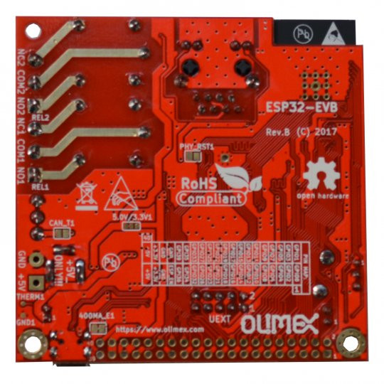
Olimex ESP32-EVB Board with Ethernet, CAN Bus, and Relays up for Sale for 26 Euros
One of the new feature of Espressif ESP32 SoC over ESP8266 is the inclusion of an Ethernet MAC interface, but so far few boards come with an RJ45 jacks. ESP32 Monster board is an option, also including an OLED Display and CAN Bus, and sold on Tindie for $35, but Olimex has now stocked their ESP32-EVB board with Ethernet, CAN Bus, and two relays, and you can purchase it for 26 Euros per unit, and less in larger quantities.
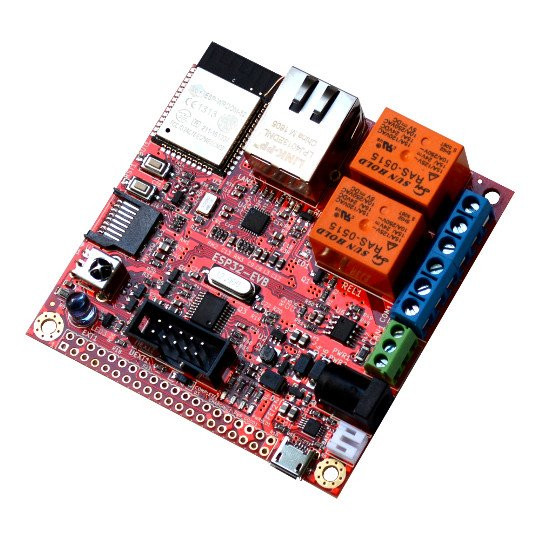 Olimex ESP32-EVB Rev. B specifications:
- Wireless Module – ESP32-WROOM32 module with 802.11 b/g/n WiFi and Bluetooth LE
- Wired Connectivity – 10/100M Ethernet with RJ45 jack (via LAN8710A)
- External Storage – micro SD slot
- Relays – 2x 10A/250VAC relays with LED status
- Expansion
- 40-pin GPIO female header (2.54mm pitch)
- UEXT connector for sensors and modules
- CAN Bus
- USB – 1x micro USB port for debugging (CH340T) and power
- Misc – Reset and user buttons, IR receiver and transmitter with up to 5 meter range
- Power Supply
- 5V via power jack or micro USB port
- LiPo charger and step up converter allowing ESP32-EVB to run from LiPo battery
- Dimensions – 75 x 75 mm
The specifications are a little different compared to the Rev. A prototype shown in February, as they added IR transmitter and receiver, a CAN bus, and a micro USB port for debugging, which increases the size of the PCB, and also explains why the price went up from an expected 22 Euros to 26 Euros for the final board.
 The board is open source hardware, and you’ll find hardware design files on Github. The software directory is empty for now, but the Tindie page about ESP32 Monster board indicates that “Ether and CAN programming requires ESP-IDF environment and still not by Arduino IDE”, so if you want to use the latter you may have wait a little longer. Olimex is also planning for a color 2.8″ LCD 320×240 pixel display board connected through UEXT header.
↧
ACT Power unveils its Project-X A1 production ready development board at Computex 2017
These days developer boards are a dime a dozen, but Taiwanese ACT Power has taken a different approach from most companies out there by making their addition production ready. The Project-X A1 is the first in what is expected to be a series of boards that will utilize the same mezzanine board connectors, to make it easy to change hardware platforms over time.
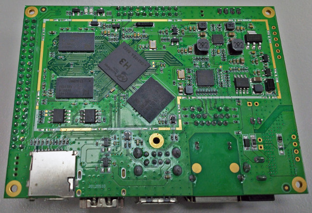
Click to Enlarge
The board on display at Computex is still an early prototype and some things will change before the final product launches. Specification wise we’re looking at:
- SoC – Allwinner H3 quad core Cortex A7 processor @ 1.2 GHz with Mali-400MP2 GPU @ 600 MHz
- System Memory – 1 GB DDR3 Storage
- 8GB eMMC flash, SD card slot
- Video Output – 1x HDMI 1.4a up to 4K @ 30 Hz
- Audio Output – HDMI, I2S via pin-header
- Connectivity – Gigabit Ethernet with optional PoE support
- USB – Two full size USB ports, 1x micro USB OTG port
- Expansion headers – 40-pin “common” header to Project-X boards, 20-pin header for 10/100Mbps Ethernet, serial port and chassis buttons.
- Debugging – 4-pin serial console header
- Misc – 2x LEDs for power and status, rear reset button, power and UBoot buttons.
- Power Supply – 12V via barrel plug or internal 2-pin header, optionally via PoE.
- Dimensions – 100×72 mm (Pico-ITX)
- Weight – ~60 grams
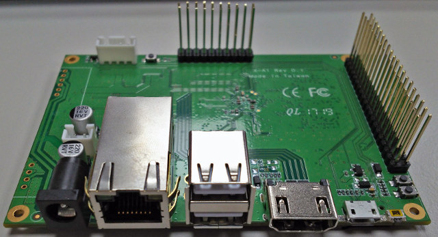
Click to Enlarge
Although the hardware itself doesn’t distinguish the A1 board from many of its competitors, the plan is to offer a range of mezzanine modules for the expansion header. The ones pictured are only dummy mockups that were done for Computex, but it gives an idea of what’s being developed. The basic mezzanine board is simply a pin-header converter that allows to use of Raspberry Pi hats, although this would require some software re-jigging of the GPIO’s to make things work. The second board adds Wi-Fi as well as the option to add a 3G/4G USB only mini PCIe card. This version also has an industrial serial port header on it. An “IoT” friendly option and various industrial automation solutions are also planned to be offered.
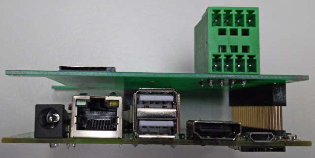
Click to Enlarge
Unlike most expansion headers, the Project-X header has support for USB 2.0 and 12V power, which means that those looking to develop their own mezzanine boards can add things relays and various USB devices without worrying about about having to use external connectors. The secondary connector allows for the addition of a 10/100Mbps Ethernet port, a third serial port (the 40-pin connector supports two already), as well as connect chassis LEDs and buttons. In the dummy boards this connector is interfacing with the mezzanine boards, but this is unlikely to be the case for many production solutions.
Courtesy of its Pico-ITX form factor, the Project-X A1 should be pretty straightforward to use in commercial products without the need of a highly customized housing. ACT Power is planning to release an Intel based version of Project-X later this year, but didn’t share details on which CPU would be used. The expansion header specification will also be shared closer to launch and ActPower will work with any potential customers to develop custom mezzanine boards. Unlike many development boards, this is not an open source project, but support for Ubuntu and Debian is expected.
↧
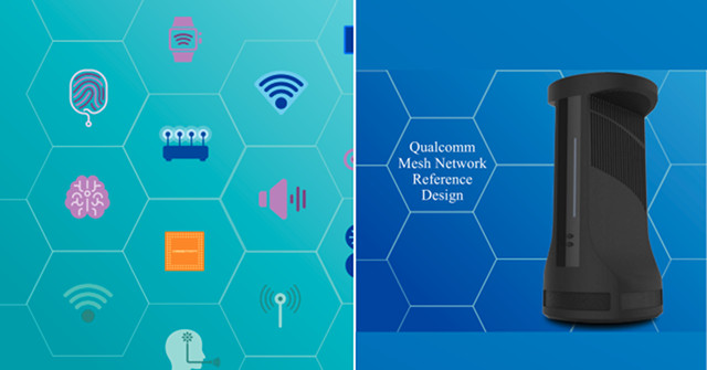
Qualcomm Unveils Mesh Networking WiFi Router / Gateway Reference Design Powered by IPQ40x8/9 NSoC
Home > Hardware, Qualcomm Atheros > Qualcomm Unveils Mesh Networking WiFi Router / Gateway Reference Design Powered by IPQ40x8/9 NSoC
Qualcomm Unveils Mesh Networking WiFi Router / Gateway Reference Design Powered by IPQ40x8/9 NSoC
Qualcomm has just announced the Qualcomm Mesh Networking Platform for OEM and broadband providers to design home WiFi routers/gateways capable of providing “robust and consistent connectivity”, and feature voice control capabilities, centralized management and security, and a range of mesh system features.
In order to speed up adoption the the platform, the company introduced the Qualcomm Mesh Networking Reference Design with the following key features & benefits:
- Network System-on-Chip (NSoC) – Qualcomm IPQ40x8/9 network system-on-chip with four Cortex A7 cores, 802.11ac WiFi 2×2+2×2, network and crypto accelerators
- Qualcomm Wi-Fi Self-Organizing (SON) feature suite will ensure corner-to-corner Wi-Fi coverage, easy set-up, automatic management and traffic optimization, as well as additional security safeguards.
- Carrier-Grade features with Wi-Fi SON APIs, cloud-based diagnostics
- Integrated voice capabilities thanks to built-in microphone array and speaker, voice recognition software, and APIs support for popular cloud-based assistant applications.
- Variety of backhaul options to be used to maximize the performance of mesh networks (802.11ac, 802.11ad, 802.11ax, or Powerline technologies)
- Qualcomm IoT Connectivity Feature Suite will ensure simultaneous use of Wi-Fi, Bluetooth, CSRmesh, and 802.15.4 connectivity
Qualcomm is – as usual – light on details, but at least that means your future WiFi routers will work better by using mesh technology for better coverage in your home, and may also be used as your IoT gateway, and Google Home/Amazon Echo replacement.
Via AnandTech
↧
↧
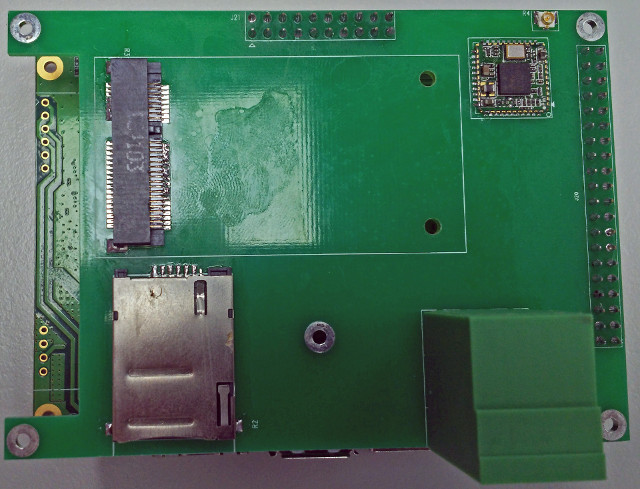
OpenH PULSAR and QUASAR Boards Add 4G LTE Cat M1, or Cat 4/1 to Raspberry Pi Boards
We’ve seen a bunch of IoT boards with 2G connectivity recently including Orange Pi 2G-IoT, Wio GPS, and Nadhat, but while in some countries 2G will still work for many years, those boards are already obsolete – or soon will be – in many other countries. However, finding low cost 3G / 4G boards is more difficult, and while one solution is to use 3G or 4G USB dongles, “OpenH – Open Hardware” – part of KLiP Industries – has designed two boards with 4G connectivity provided by Quectel modules.
OpenH PULSAR Board
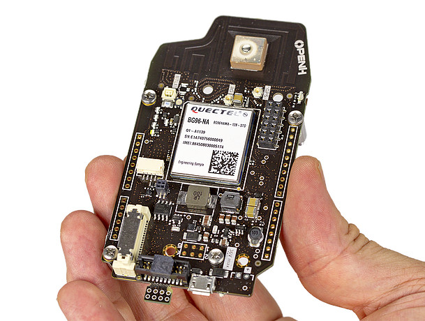 PULSAR board is compatible with Arduino Zero and features the following specifications:
- MCU – Atmel/Microchip SAMD21 ARM Cortex M0+ MCU (the as the one used in Arduino Zero)
- Connectivity
- Security – Dedicated management CPU with crypto engine
- Power Supply 10W digital power supply and battery charger with direct solar input
- FCC and Carrier certified
The board can work in standalone mode, but if needed, a Raspberry Pi Zero can optionally be mounted to the board. PULSAR is designed for low-bandwidth projects up to 200 kbps, support OTA firmware updates, and can work with the cloud provider of your choice.
OpenH QUASAR Raspberry Pi HAT Board
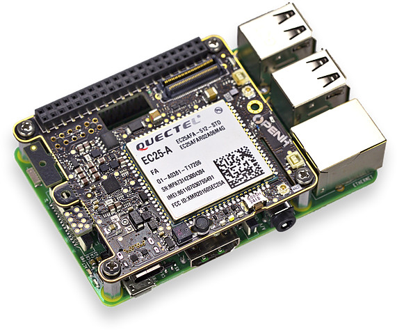 If your project needs more bandwidth, you can use QUASAR boards instead on a Raspberry Pi 2/3 board:
- Connectivity
- Expansion connectors
- Security – Dedicated management CPU with crypto engine
- Power Supply – 25W digital power supply and battery charger with direct solar input
- FCC and Carrier certified
You’ll get up to 150 Mbps bandwidth using LTE Cat 4 module, and just like the other board is can support OTA firmware update, and popular cloud services like Amazon Web Service (AWS) IoT, Azure IoT Hub, IBM BlueMix, Google Cloud for IoT, ThingSpeak, etc…
Installation and IP67 Enclosure
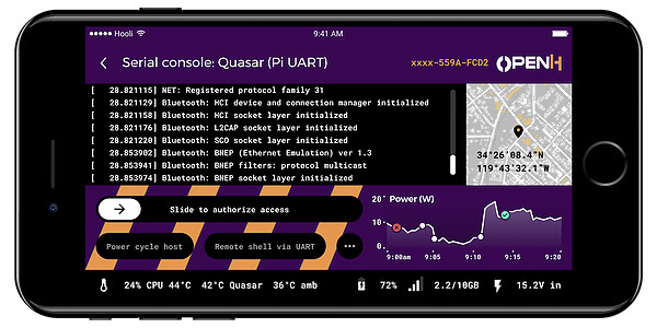
OpenH explains Bluetooth and NFC are for installation and maintenance, and they appears to have a mobile to access the serial console, authorize access, reboot the board, check GPS coordinates…. over Bluetooth, as shown above using QUASAR board.
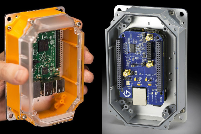
Click to Enlarge
Many such long range IoT projects are designed to be placed outdoor, so the company also offer Rubicon IP67 weatherproof enclosure that works with both 4G boards, as well as Raspberry Pi, Arduino, BeagleBone, etc.. and is high enough for one or more add-ons board thanks to a selection of shallow or deep covers. The photo above shows the case with a Raspberry Pi board (left) and Beaglebone Black + PRUDAQ cape (right).
The downside is that the board are not available yet, pricing is unknown, and documentation is very limited right now. If you are interested, you can register your email on openh.io website by clicking on Pre-order Now button. Rubicon IP67 enclosure is available now for $35 plus shipping.
[embedded content]
↧
WebAssembly is a Cross-Platform, Cross-Browser Solution for High Performance Code in Web Browsers
![]() Most code running in a web browser runs much slower than native code (C/C++/ assembly), and it’s fine for many applications, but some others requiring higher performance like software video decoding would have to relies on native code, initially provided via browser plugins, but then Google introduced PNaCL (Portable Native Client) allowing to run native code on multiple targets (ARM, Intel, etc..) but in Chrome browser only, and now one of Chrome developers has explained that the community has moved to WebAssembly.
Most code running in a web browser runs much slower than native code (C/C++/ assembly), and it’s fine for many applications, but some others requiring higher performance like software video decoding would have to relies on native code, initially provided via browser plugins, but then Google introduced PNaCL (Portable Native Client) allowing to run native code on multiple targets (ARM, Intel, etc..) but in Chrome browser only, and now one of Chrome developers has explained that the community has moved to WebAssembly.
WebAssembly works just as well as PNaCl, and is already natively supported by Chrome and Firefox, with support added to preview versions of Microsoft Edge and Apple Safari browsers.Since it works just as well as PNaCL, and adoption of the later is low enough, Google decided to drop support for PNaCl in the Chrome browser in Q1 2018, except inside Chrome Apps and Extensions.

WebAssembly Unity WebGL Game Demo
To get a feel for the performance and capabilities, you can find a few demos on WebAssembly website:
The latter demo also compares the performance for the same task between WebAssembly and JavaScript, and in the screenshot below we can see WASM (short name for WebAssembly) is 80% faster than JS (JavaScript) while applying “Sunset” filter to the video in Firefox.
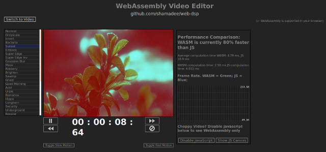
Click to Enlarge
You’ll find the source code of the demo in Github. It’s still far from the performance of desktop app, but a big improvement over JavaScript.
If you’ve ever made a native web app relying on PNaCl, Google has provided a set of recommendation to help migration to WASM.
↧
Infineon Claims to Have Implemented Post-Quantum Cryptography on a Contactless Security Chip
Today we protect systems, data, and communication using encryption keys of various lengths together with secure algorithms, and after a quick check, I found out banking websites are using 128-bit to 256-bit keys for secure (TLS v1.2) communication, and my Linux system is using a 4096-bit RSA key for secure communication over SSH. According to an Infineon press release, such key length are suitable for secure communication today, and current computer do not have sufficient processing power to break encryption, but with the advance of Quantum computer, even RSA-2048 keys won’t be secure, which means in 15 to 20 years all data encrypted (and stored) today with such keys would theoretically be accessible in the clear.
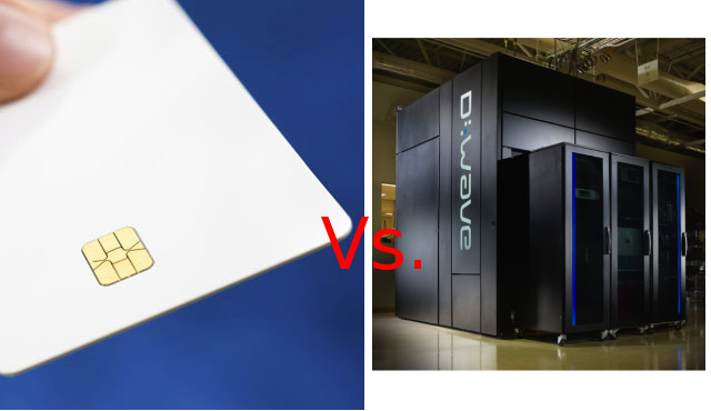
That’s why the company has been working on next-generation post-quantum cryptography (PQC), and recently demonstrated the first PQC implementation on a commercially available contactless security chip, as used for electronic ID documents.
The company explains further:
Security experts at Infineon’s Munich headquarters and the Center of Excellence for contactless technologies in Graz, Austria, made a breakthrough in this field. They implemented a post-quantum key exchange scheme on a commercially available contactless smart card chip. Key exchange schemes are used to establish an encrypted channel between two parties. The deployed algorithm is a variant of “New Hope”, a quantum-resistant cryptosystem also explored successfully by Google on a development version of the Chrome browser.
The main challenge was to keep the small chip size and memory with the more complex PQC algorithm, and also to get the transaction to execute in a reasonable amount of time. They managed to do this on a commercial available security chip without requiring additional memory space. Those advances should also for security equivalent to today’s RSA and ECC at a time when quantum computer become available. Going forward, there will need to be one or more PQC algorithms standardized before government and industries mandate the migration.
Via ElectronicsWeekly.
↧