At the beginning of the month I shows how to assemble RabbitMax Flex, a Raspberry Pi HAT compliant add-on board for Raspberry Pi boards with 40-pin header, that targets IoT and home automation project with its relay, IR transmitter and receiver, I2C headers for sensors, buzzer, RGB LED, and more. Since I’ve already described the hardware, I’ve spend some time this week-end following the user’s guide to play around with the board using a Raspberry Pi 2 board, and try various features.
![rabbitmax-flex-demo]()
The user’s manual explains that you need the latest version of Raspbian, but I’d not played with my Raspberry Pi 2 board for a while, so the kernel and firmware were quite old:
|
|
uname -a
Linux raspberrypi 4.1.7-v7+ #817 SMP PREEMPT Sat Sep 19 15:32:00 BST 2015 armv7l GNU/Linux
pi@raspberrypi ~ $ /opt/vc/bin/vcgencmd version
Sep 23 2015 12:12:01
Copyright (c) 2012 Broadcom
version c156d00b148c30a3ba28ec376c9c01e95a77d6d5 (clean) (release)
|
So the first thing I had to do was to upgrade Raspbian. There are basically two options to upgrade, either downloading and dumping the latest Raspbian firmware image to your micro SD card, and update it from the command line, for example through SSH, and I went with the latter what :
|
|
sudo apt-get update
sudo apt-get dist-upgrade
|
This took several hours on my board, so in hindsight it may not have been the best options. In order to complete the update, I had to reboot the board, and could confirm the Linux kernel and Broadcom firmware had both been updated:
|
|
pi@raspberrypi ~ $ uname -a
Linux raspberrypi 4.4.26-v7+ #915 SMP Thu Oct 20 17:08:44 BST 2016 armv7l GNU/Linux
pi@raspberrypi ~ $ /opt/vc/bin/vcgencmd version
Oct 20 2016 14:57:49
Copyright (c) 2012 Broadcom
version b1f1c64dd836f2324e1105db36f8c356a11b2d54 (clean) (release)
|
Now we can install I2C tools and vim in order to play with RabbitMax Flex sensors:
|
1
|
sudo apt-get install -y git i2c-tools vim
|
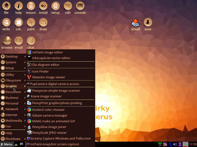
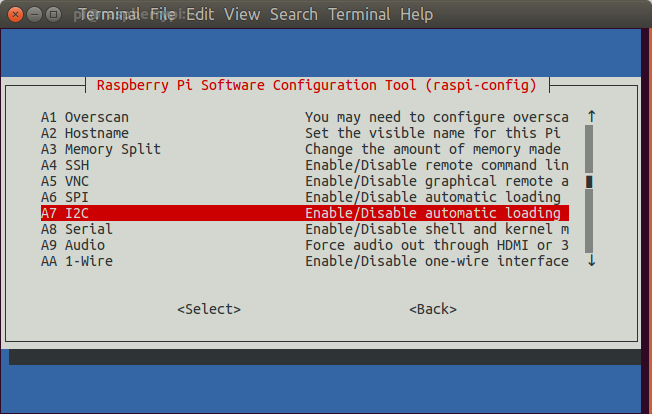
We also need to enable I2C though raspi-config:
and go to Advanced->A7 I2C to enable I2C.
![raspberry-pi-i2c-configuration]()
We need to reboot the board again to make sure I2C drivers are automatically loaded at boot time.
RabbitMax Flex user’s manual recommends to use a USB to serial debug at this stage, but it’s just as simple, and IMHO more convenient, to execute command using an SSH terminal. So let’s carry on with software installation with some more dependencies and wiringPi library to control GPIOs:
|
|
sudo apt-get install -y git git-core vim python-dev python-rpi.gpio
cd ~
git clone git://git.drogon.net/wiringPi
cd wiringPi
./build
|
The system configuration is now complete, and we can use some code samples provided by Leon Anavi, RabbitMax Flex’s developer:
|
|
cd ~
git clone https://github.com/RabbitMax/rabbitmax-examples.git
cd rabbitmax-examples/flex
|
There are eight samples in the directory available in C (using wiringPi library) and/or Python (using python-rpi.gpio):
- button – Sample to detect when the button is released
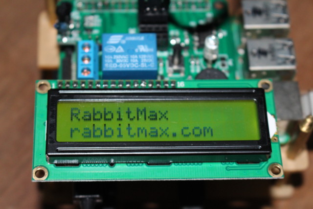
- lcd – Displays “RabbitMax rabbitmax.com” on the LCD display (C language only)
- rgb-led – Changes RGB LED color every two seconds in loop between red, green and blue
- sensor-light – Displays BH1750 light sensor intensity in Lux (C language only)
- buzzer – Turns on the on-board buzzer (beep sample), and plays Star Wars music (starwars sample).
- relay – Turns on the relay for 3 seconds, and turn it off
- sensor-humidity – Prints temperature & humidity values from HTU21D I2C sensor (C language only)
- sensor-temperature – Prints temperature & pressure values from BMP180 I2C sensor (C language only)
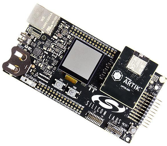
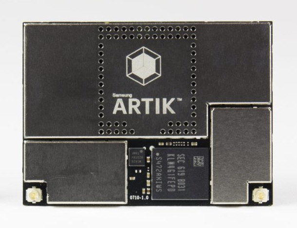
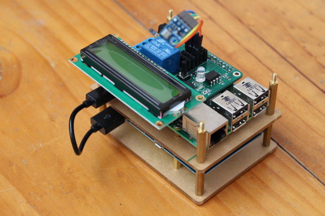
![RabbitMax Flex LCD Sample]()
RabbitMax Flex LCD Sample
The first sample I tried was the C code for the button:
|
|
pi@raspberrypi ~/rabbitmax-examples/flex/button/c $ make
gcc -c -o button.o button.c -I.
gcc -o button button.o -I. -lwiringPi
pi@raspberrypi ~/rabbitmax-examples/flex/button/c $ sudo ./button
Press the button and release it after at least a second.
Button released!
Button released!
|
WiringPi requires to run the code as root/sudo, but it might be to change some permissions to fix this. The Python sample is even easier to use:
|
|
pi@raspberrypi ~/rabbitmax-examples/flex/button/c $ cd ../python/
pi@raspberrypi ~/rabbitmax-examples/flex/button/python $ python ./button.py
Press the button and release it after at least a second.
Button released!
Button released!
|
It’s much more fun to use the board with some I2C sensors (up to 5 are supported through the headers on the add-on board), andLeon send me a BMP180 temperature and pressure sensor, and I also connected a Grove module (accelerometer) I got from Wio Link Starter Kit. i2cdetect had no problems detecting both:
|
|
pi@raspberrypi ~ $ sudo i2cdetect -y 1
0 1 2 3 4 5 6 7 8 9 a b c d e f
00: – – – – – – – – – – – – –
10: – – – – – – – – – – – – – – – –
20: – – – – – – – – – – – – – – – –
30: – – – – – – – – – – – – – – – –
40: – – – – – – – – – – – – 4c – – –
50: – – – – – – – – – – – – – – – –
60: – – – – – – – – – – – – – – – –
70: – – – – – – – 77
|
0x77 address is used by BMP180 sensor, while 0x4c address is for the grove module.
So now that we’ve made sure the BMP180 sensor has been detected we can try the sample:
|
|
pi@raspberrypi ~/rabbitmax-examples/flex/sensor-temperature/c $ make
gcc -c -o BMP180.o BMP180.c -I.
gcc -c -o rabbitmax-sensor-temperature.o rabbitmax-sensor-temperature.c -I.
gcc -o rabbitmax-sensor-temperature BMP180.o rabbitmax-sensor-temperature.o -I. -lwiringPi -lm
pi@raspberrypi ~/rabbitmax-examples/flex/sensor-temperature/c $ sudo ./rabbitmax-sensor-temperature
RabbitMax Temperature and Barometric Pressure Sensor
Temperature 27.7 C
Pressure 978.72 hPa
|
The reported temperature matches the actual temperature in my room.
I initially planned to write a sample demo control my aircon using the button and the temperature sensor, so I also had to configure LIRC both to capture my aircon remote control codes, and send back the codes though the IR transmitter.
Again this is very well explained in the user’s guide, and I started by installed LIRC.
|
|
sudo apt-get update
sudo apt-get install -y lirc
|
There’s no support in raspi-config for LIRC, so we have to edit /etc/modules and add the IR pins by adding the following lines:
|
|
lirc_dev
lirc_rpi gpio_in_pin=18 gpio_out_pin=17
|
We also have to changed four lines in /etc/lirc/hardware.conf:
|
|
# /etc/lirc/hardware.conf
#
# Arguments which will be used when launching lircd
LIRCD_ARGS=“–uinput”
...
# Run “lircd –driver=help” for a list of supported drivers.
DRIVER=“default”
# usually /dev/lirc0 is the correct setting for systems using udev
DEVICE=“/dev/lirc0″
MODULES=“lirc_rpi”
|
and finally I had to edit /boot/config.txt to add lirc support to dtoverlay:
|
1
|
dtoverlay=lirc-rpi,gpio_in_pin=18,gpio_out_pin=17
|
Configure is done, and we can restart the Raspberry Pi board to make sure the changes are applied:
Now I’m going to capture key code from my aircon remote. First, we need to stop the service, and list of available remote key names:
1
2
3
4
5
6
7
8
9
10
11
12
13
14
15
16
17
|
sudo systemctl stop lirc
irrecord –list-namespace
KEY_0
KEY_102ND
KEY_1
KEY_2
KEY_3
...
KEY_DOLLAR
KEY_DOT
KEY_DOWN
KEY_DVD
...
KEY_PLAYPAUSE
KEY_POWER
KEY_POWER2
...
|
Now in theory I can assign remote codes to the actual output from my aircon remote, and the idea was to use KEY_POWER for the remote power button, and KEY_DOWN to set the temperature to 25 C with the command:
|
1
|
irrecord -d /dev/lirc0 ~/lircd.conf
|
Sadly, maybe one out of 25 key presses from my remote control were detected. Maybe an issue with the protocol used or timing, but I found out that I had no such problem with my TV remote control, and could complete the setup:
Press RETURN now to start recording.
……………………………………………………………………..
Found const length: 107981
Please keep on pressing buttons like described above.
……………………………………………………………………..
Space/pulse encoded remote control found.
Signal length is 67.
Found possible header: 9018 4450
Found trail pulse: 590
Found repeat code: 9019 2217
Signals are space encoded.
Signal length is 32
Now enter the names for the buttons.
Please enter the name for the next button (press <ENTER> to finish recording)
KEY_POWER
1
2
3
4
5
6
7
8
9
10
11
12
13
14
15
16
17
18
19
20
21
22
23
24
|
It is very important that you press many different buttons and hold them
down for approximately one second. Each button should generate at least one
dot but in no case more than ten dots of output.
Don‘t stop pressing buttons until two lines of dots (2×80) have been
generated.
Press RETURN now to start recording.
................................................................................
Found const length: 107981
Please keep on pressing buttons like described above.
................................................................................
Space/pulse encoded remote control found.
Signal length is 67.
Found possible header: 9018 4450
Found trail pulse: 590
Found repeat code: 9019 2217
Signals are space encoded.
Signal length is 32
Now enter the names for the buttons.
Please enter the name for the next button (press <ENTER> to finish recording)
KEY_POWER
|
I configured three keys:
|
|
sudo irsend LIST /home/pi/lircd.conf “”
irsend: 00000000000010ef KEY_POWER
irsend: 00000000000008f7 KEY_0
irsend: 000000000000906f KEY_MUTE
|
That means that my test/demo project had now become rather silly, as instead of turning on my aircon when it gets hot, I’d turn on the TV 🙂 But I guess it’s good enough for a review, and as a learning experience.
Now we can backup the old lirc config, replace it with ours, and restart LIRC daemon:
|
|
sudo mv /etc/lirc/lircd.conf /etc/lirc/lircd-backup.conf
sudo mv ~/lircd.conf /etc/lirc/lircd.conf
sudo systemctl start lirc
|
I could also confirm I could turn on and off the TV with my Raspberry Pi 2 and RabbitMax Flex board using the following command:
|
1
|
sudo irsend SEND_ONCE /home/pi/lircd.conf KEY_POWER
|
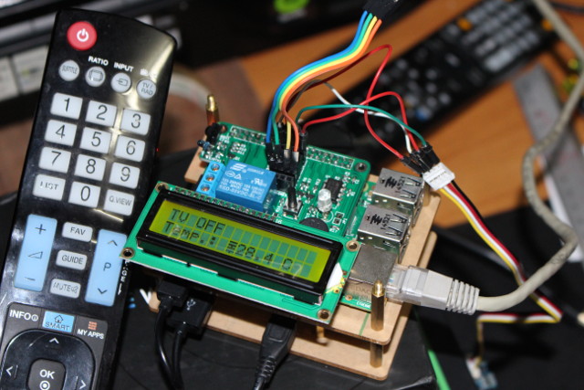
From there, it was quite straightforward to write my “useless TV demo” based on code from the samples that turns on and off the TV whenever I release the push button, or when the temperature crosses 30 Celsius, and showing the power status and temperature on the LCD display:
#include “BMP180.h”
/* LCD Display defines */
#define LCDROWS 2
#define LCDCOLS 16
#define LCDBITS 4
#define LCDRS 7
#define LCDSTRB 29
#define LCDDATA0 2
#define LCDDATA1 3
#define LCDDATA2 12
#define LCDDATA3 13
/* GPIO number definitions for WiringPi library */
#define ButtonPin 14
#define BuzzerPin 22
void beep() {
int i;
for (i=0; i<250; i++) { /* Beep for around one second */
digitalWrite(BuzzerPin, LOW);
delay(2);
digitalWrite(BuzzerPin, HIGH);
delay(2);
}
}
int main()
{
static int lcdHandle = 0;
if (-1 == wiringPiSetup()) {
printf(“setup wiringPi failed!n”);
return 1;
}
/* Set GPIO pins direction */
pinMode(ButtonPin, INPUT);
pullUpDnControl(ButtonPin, PUD_UP);
pinMode(BuzzerPin, OUTPUT);
/* Configure LCD display, assume TV is OFF initially */
lcdHandle = lcdInit(LCDROWS, LCDCOLS, LCDBITS, LCDRS, LCDSTRB, LCDDATA0, LCDDATA1, LCDDATA2, LCDDATA3, 0, 0, 0, 0);
lcdClear(lcdHandle);
lcdPosition(lcdHandle, 0, 0);
lcdPuts(lcdHandle, “TV OFF”);
/* Initialize BMP180 Sensor */
int fd = wiringPiI2CSetup(BMP180_I2CADDR);
if (0 > fd) {
fprintf(stderr, “ERROR: Unable to access RabbitMax temperature sensor: %sn”, strerror (errno));
return 1;
}
if (0 > begin(fd)) {
fprintf(stderr, “ERROR: RabbitMax temperature sensor not foundn”);
return 1;
}
/* Check whether button has been released or temperature over 30C, and change TV status */
while(1)
{
static int OldButtonStatus = HIGH; /* Previous value of GPIO Pin */
static int TVStatus = LOW; /* OFF */
static double OldBMP180Temp = 0; /* Store temperature value */
double BMP180Temp = 0; /* Current temperature value */
int ButtonStatus = digitalRead(ButtonPin); /* Current value of GPIO pin */
/* Get temperature from BMP180 I2C sensor */
getTemperature(fd, &BMP180Temp);
if ((OldBMP180Temp < 30) && (BMP180Temp >= 30)) {
/* If temp get over 30 C, simulate button released and set TV status to OFF (to turn it ON) */
printf(“Temperature rose over 30 C…n”);
ButtonStatus = HIGH;
OldButtonStatus = LOW;
TVStatus = LOW;
}
if ((OldBMP180Temp >= 30) && (BMP180Temp < 30)) {
/* Simulate button released and set TV status to ON (to turn it OFF) */
printf(“Temperature dropped below 30 C…n”);
ButtonStatus = HIGH;
OldButtonStatus = LOW;
TVStatus = HIGH;
}
OldBMP180Temp = BMP180Temp;
if ( (HIGH == ButtonStatus) && (LOW == OldButtonStatus) )
{
if (LOW == TVStatus) { /* TV OFF, turn it on and beep for 1 second */
printf(“Turn TV On!n”);
/* Send power IR code */
system(“sudo irsend SEND_ONCE /home/pi/lircd.conf KEY_POWER”);
lcdClear(lcdHandle);
lcdPosition(lcdHandle, 0, 0);
lcdPuts(lcdHandle, “TV ON”);
beep(); /* Buzzer on */
TVStatus = HIGH;
} else { /* TV ON, turn it off */
printf(“Turn TV Off!n”);
/* Send Power IR code */
system(“sudo irsend SEND_ONCE /home/pi/lircd.conf KEY_POWER”);
lcdClear(lcdHandle);
lcdPosition(lcdHandle, 0, 0);
lcdPuts(lcdHandle, “TV OFF”);
lcdPosition (lcdHandle, 0, 1);
lcdPuts(lcdHandle, “”);
TVStatus = LOW;
}
}
/* Update Temperature value */
lcdPosition (lcdHandle, 0, 1);
lcdPrintf(lcdHandle, “Temp.: %0.1f C”, OldBMP180Temp);
OldButtonStatus = ButtonStatus;
delay(500);
}
return 0;
}
1
2
3
4
5
6
7
8
9
10
11
12
13
14
15
16
17
18
19
20
21
22
23
24
25
26
27
28
29
30
31
32
33
34
35
36
37
38
39
40
41
42
43
44
45
46
47
48
49
50
51
52
53
54
55
56
57
58
59
60
61
62
63
64
65
66
67
68
69
70
71
72
73
74
75
76
77
78
79
80
81
82
83
84
85
86
87
88
89
90
91
92
93
94
95
96
97
98
99
100
101
102
103
104
105
106
107
108
109
110
111
112
113
114
115
116
117
118
119
120
121
122
123
124
125
126
127
128
129
|
/* Useless TV demo – Turn on/off with button or temperature sensor */
#include <stdio.h>
#include <termios.h>
#include <unistd.h>
#include <errno.h>
#include <wiringPi.h>
#include <lcd.h>
#include “BMP180.h”
/* LCD Display defines */
#define LCDROWS 2
#define LCDCOLS 16
#define LCDBITS 4
#define LCDRS 7
#define LCDSTRB 29
#define LCDDATA0 2
#define LCDDATA1 3
#define LCDDATA2 12
#define LCDDATA3 13
/* GPIO number definitions for WiringPi library */
#define ButtonPin 14
#define BuzzerPin 22
void beep() {
int i;
for (i=0; i<250; i++) { /* Beep for around one second */
digitalWrite(BuzzerPin, LOW);
delay(2);
digitalWrite(BuzzerPin, HIGH);
delay(2);
}
}
int main()
{
static int lcdHandle = 0;
if (-1 == wiringPiSetup()) {
printf(“setup wiringPi failed!n”);
return 1;
}
/* Set GPIO pins direction */
pinMode(ButtonPin, INPUT);
pullUpDnControl(ButtonPin, PUD_UP);
pinMode(BuzzerPin, OUTPUT);
/* Configure LCD display, assume TV is OFF initially */
lcdHandle = lcdInit(LCDROWS, LCDCOLS, LCDBITS, LCDRS, LCDSTRB, LCDDATA0, LCDDATA1, LCDDATA2, LCDDATA3, 0, 0, 0, 0);
lcdClear(lcdHandle);
lcdPosition(lcdHandle, 0, 0);
lcdPuts(lcdHandle, “TV OFF”);
/* Initialize BMP180 Sensor */
int fd = wiringPiI2CSetup(BMP180_I2CADDR);
if (0 > fd) {
fprintf(stderr, “ERROR: Unable to access RabbitMax temperature sensor: %sn”, strerror (errno));
return 1;
}
if (0 > begin(fd)) {
fprintf(stderr, “ERROR: RabbitMax temperature sensor not foundn”);
return 1;
}
/* Check whether button has been released or temperature over 30C, and change TV status */
while(1)
{
static int OldButtonStatus = HIGH; /* Previous value of GPIO Pin */
static int TVStatus = LOW; /* OFF */
static double OldBMP180Temp = 0; /* Store temperature value */
double BMP180Temp = 0; /* Current temperature value */
int ButtonStatus = digitalRead(ButtonPin); /* Current value of GPIO pin */
/* Get temperature from BMP180 I2C sensor */
getTemperature(fd, &BMP180Temp);
if ((OldBMP180Temp < 30) && (BMP180Temp >= 30)) {
/* If temp get over 30 C, simulate button released and set TV status to OFF (to turn it ON) */
printf(“Temperature rose over 30 C…n”);
ButtonStatus = HIGH;
OldButtonStatus = LOW;
TVStatus = LOW;
}
if ((OldBMP180Temp >= 30) && (BMP180Temp < 30)) {
/* Simulate button released and set TV status to ON (to turn it OFF) */
printf(“Temperature dropped below 30 C…n”);
ButtonStatus = HIGH;
OldButtonStatus = LOW;
TVStatus = HIGH;
}
OldBMP180Temp = BMP180Temp;
if ( (HIGH == ButtonStatus) && (LOW == OldButtonStatus) )
{
if (LOW == TVStatus) { /* TV OFF, turn it on and beep for 1 second */
printf(“Turn TV On!n”);
/* Send power IR code */
system(“sudo irsend SEND_ONCE /home/pi/lircd.conf KEY_POWER”);
lcdClear(lcdHandle);
lcdPosition(lcdHandle, 0, 0);
lcdPuts(lcdHandle, “TV ON”);
beep(); /* Buzzer on */
TVStatus = HIGH;
} else { /* TV ON, turn it off */
printf(“Turn TV Off!n”);
/* Send Power IR code */
system(“sudo irsend SEND_ONCE /home/pi/lircd.conf KEY_POWER”);
lcdClear(lcdHandle);
lcdPosition(lcdHandle, 0, 0);
lcdPuts(lcdHandle, “TV OFF”);
lcdPosition (lcdHandle, 0, 1);
lcdPuts(lcdHandle, “”);
TVStatus = LOW;
}
}
/* Update Temperature value */
lcdPosition (lcdHandle, 0, 1);
lcdPrintf(lcdHandle, “Temp.: %0.1f C”, OldBMP180Temp);
OldButtonStatus = ButtonStatus;
delay(500);
}
return 0;
}
|
It works pretty well, as you can see from the video.
[embedded content]
You’ll also find the demo code on github.
Beside Raspbian, Leon is also working on “RabbitMax IoT GNU/Linux Distribution” built with the Yocto Project where all hardware configuration is done, running an MQTT server, as well as an GHTML8 web interface designed with jQuery Mobile and Node.js API.
You can get the source code for that, as well as the documentation, C & Python sample projects, tools, and later on KiCAD files on RabbitMax github’s account, as well as some extra info on RabbitMax.com website. You can purchase the board now for $49.90 on Tindie.com without the LCD nor sensors, but it might be a good idea to wait for the crowdfunding campaign that should start shortly, with the board offered for half the Tindie price, and probably some kits with LCD, and sensors.
Tweet At the beginning of the month I shows how to assemble RabbitMax Flex, a Raspberry Pi HAT compliant add-on board for Raspberry Pi boards with 40-pin header, that targets…
 MK809V-4K HDMI TV dongle specifications: